


49
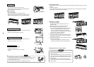
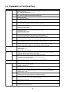
4-2. Explanation of Functional Parts
Functional part name Functional outline
SV3A
(Connector CN324: Red)
Closed : Allows oil to collect/remain in the oil tank.
Open : Allows oil to exit the oil tank.
SV3B
(Connector CN313: Blue)
Open : Allows oil to return to the outdoor unit via the balance pipe.
SV3C
(Connector CN314: Black)
Open : Pressurizes the oil tank..
SV3D
(Connector CN323: White)
Open : Supplies oil to the compressor from the oil separator.
SV3E
(Connector CN323: White)
Open : Turns on during operation and balances oil between compressors.
SV2
(Hot gas bypass) (Connector CN312: White)
1) Low pressure release function
2) High pressure release function
3) Gas balance function during stop time
SV4 1
SV4 2
(Gas balance control for compressor start-up) (Connector CN311: Blue)
1) For gas balance start
2) High pressure release function
3) Low pressure release function
SV5
(Connector CN310: White)
1) Increase of No. of heating indoor units, Gas balance function in defrost time
2) Low-pressure balance function of discharge gas pipe during all cooling operation
SV6
(Connector CN309: White)
1) Liquid bypass function for discharge temp. release (Cooling bypass circuit)
SV11
(Connector CN322: White)
1) For shutdown discharge gas (During all cooling operation and defrost operation)
Solenoid valve
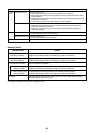
SV12
(Connector CN319: White)
1) Flow-rate control function of refrigerant to sub heat exchanger during simultaneous operation
2) Flow-rate control function of refrigerant to sub heat exchanger during defrost operation
4-way valve
(Connector CN317: Blue)
1) Cooling/Heating selection
2) Reverse defrost
3) Main-/Sub-heat exchanger selection
PMV1, 2
(Connector CN300, 301: White)
1) Super heat control function during all heating operation and mainly heating, partly cooling operation
2) Under-cool adjustment function during all cooling operation
3) Divided flow control function during mainly cooling, partly heating operation
Pulse motor
valve
PMV3
(Connector CN302: Red)
1) For flow-rate control of sub heat exchanger during simultaneous operation
(Control function of heating divided flow)
2) A function preventive high pressure up during all cooling or all heating operation
Oil separator
1) Prevention for early drop of oil level (Decrease of flow-out of discharge oil to cycle)
2) Reserve function of surplus oil
TD1, TD2
(TD1: Connector CN502: White, TD2: Connector CN503: Pink)
1) Protection of compressor discharge temp.
2) Releasing of discharge temp.
TS1
(Connector CN504: White)
1) Controls super heat of PMV1 and 2 during all heating operation and simultaneous operation
TS2
(Connector CN522: Black)
1) Controls indoor oil recovery during all cooling operation and mainly cooling, partly heating operation
2) Detects overheat of cycle.
TE
(Connector CN505: Green)
1) Controls defrost during all heating operation and simultaneous operation.
2) Controls outdoor fan during all heating operation and simultaneous operation.
TK1: Connector CN514: Black, TK2: Connector CN515: Green,
TK3: Connector CN516: Red, TK4: Connector CN523: Yellow
TK1, TK2,
TK3, TK4,
1) Judges oil level of compressor.
TL
(Connector CN521: White)
1) Detects under-cool during all cooling operation and simultaneous operation.
Temp. sensor
TO (Connector CN507: Yellow)
1) Detects external ambient temperature.