


163
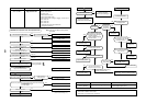
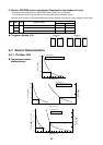
9-6. 7-Segment Display Function
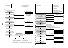
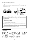
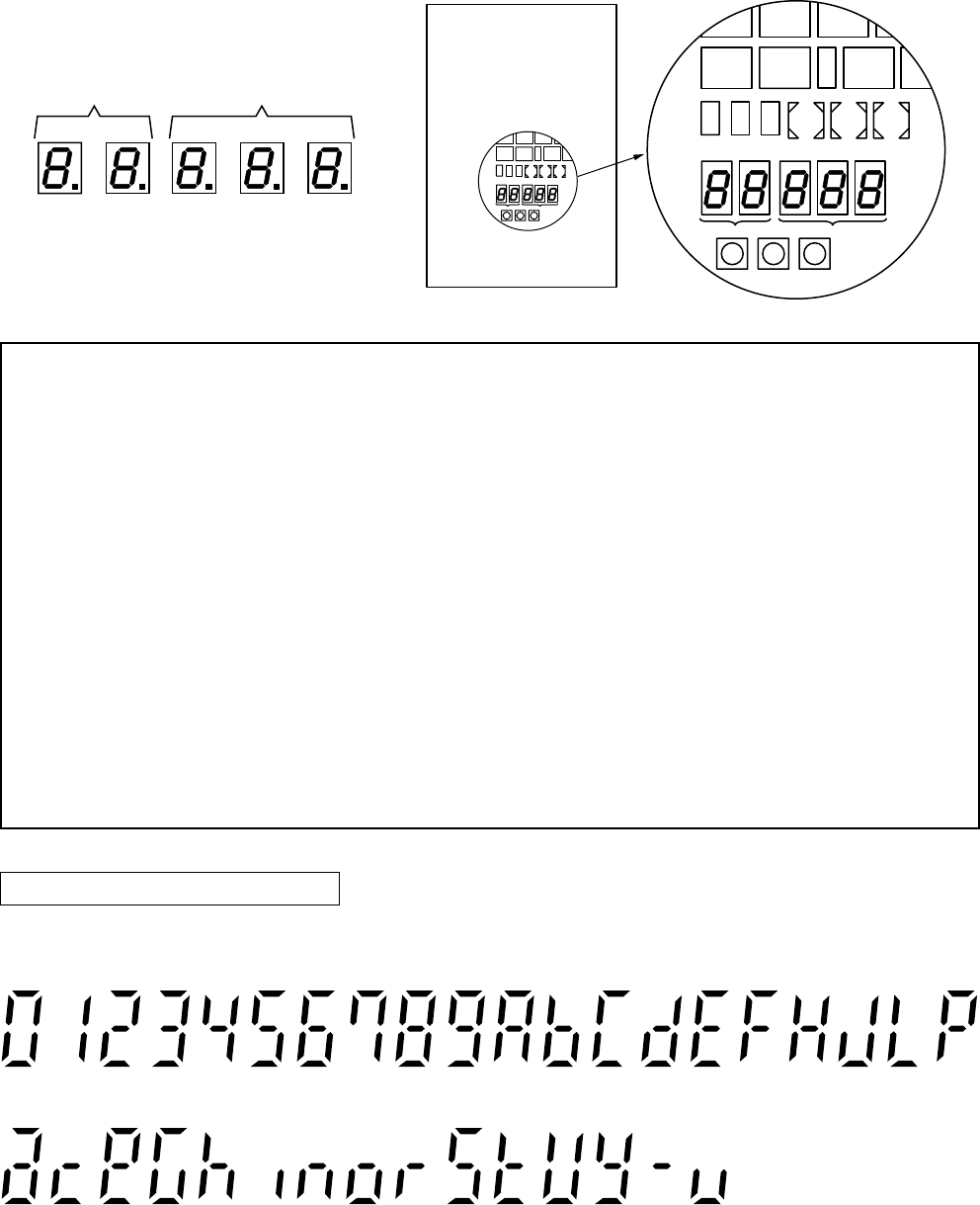
n 7-segment display on the outdoor unit (Interface P.C. board)
On the interface control P.C. board, a 7-segment LED is provided to check the operating status.
The displayed contents are changed by combining the setup numbers of the rotary switches (SW01, SW02
and SW03) on the I/F P.C. board.
2nd.
place
1st.
place
7-segment
display A
7-segment
display B
3rd.
place
2nd.
place
1st.
place
D602 D603 D604D600
CN30
SW08SW06
CN31
CN32
SW04
D601
SW01
Display A
Display B
SW02 SW03
SW05 SW15
SW07 SW09
D602 D603 D604D600
CN30
SW08SW06
CN31
CN32
SW04
D601
SW01
Display A
Display B
SW02 SW03
SW05 SW15
SW07 SW09
Interface P.C. board
a
0
c
1
e
2
G
3
h
4
i
5
n
6
o
7
r
8
S
9
t
A
V
b
y
C
–
d
u
EFHJLP
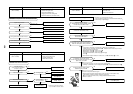
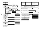
u Check procedure when the system has stopped due to an trouble
When the system has stopped due to an trouble in the outdoor unit, execute the follow-
ing check procedure.
1. Open the panels of the outdoor unit, and then check the 7-segment display.
The check code is shown on the right side of 7-segment display B.
[U1] [¡¡¡] ([¡¡¡]: Check code)
∗ Rotary switch setup for confirming the check code: SW01 [1], SW02 [1], SW03 [1].
However the check code [OOO] is displayed for 3 seconds and the sub-code [OOO] for 1 second
are alternately displayed if a sub-code is provided.
2. Confirm the check code, and then follow the check procedure detailed for the diagnosis of the fault.
3. [U1] [E28] on the 7-segment display means an error on the follower unit. change.
Push and hold switch SW04 on the header unit for 2 seconds or more.
Only the fan of the outdoor unit with a fault will operate. Open the panel of the corresponding unit, and
then confirm the ceck code shown on the 7-segment display.
4. Perform the check procedure based on each check code diagnosis.
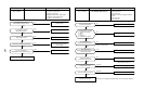
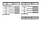
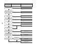
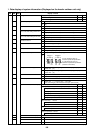
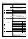
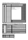
How to read the check display
7-segment display