


210
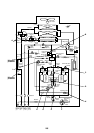
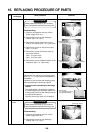
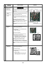
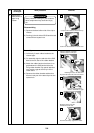
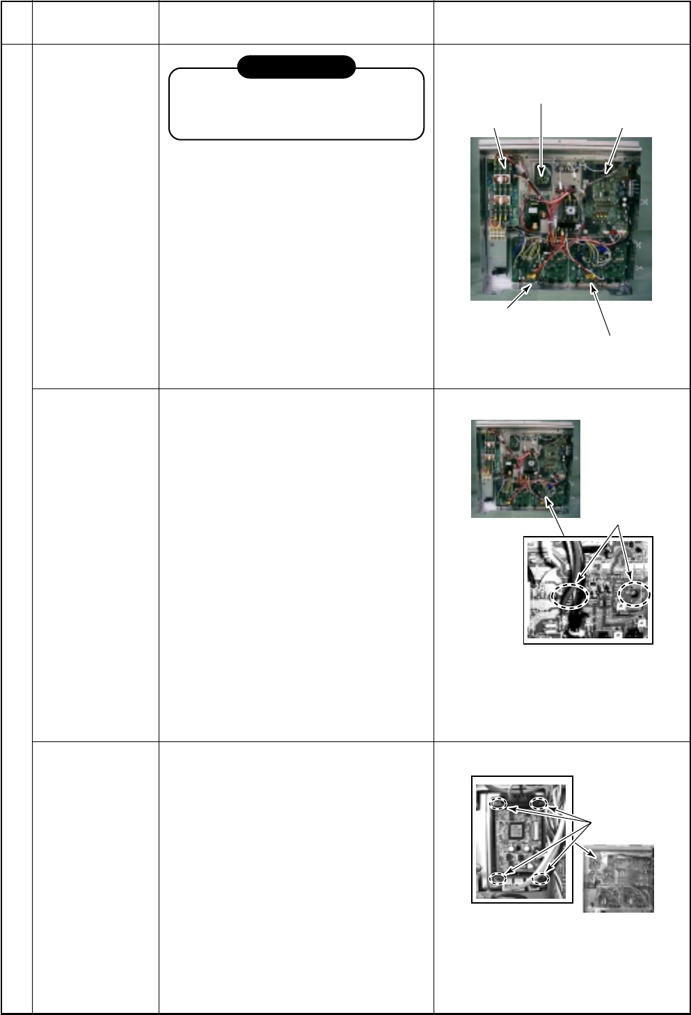
4. IPDU P.C. board for fan
1. Noise filter
P.C. boards
2. Interface P.C. board
(Control P.C. board)
3. IPDU P.C. board
(For driving of compressor 1)
3. PDU P.C. board
(For driving of compressor 2)
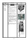
2)Screw
3)Screw
No.
5
Part to be
exchanged
Inverter assembly
M Removal of P.C.
board and
electric parts
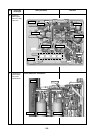
1. Noise filter P.C.
board
2. Interface P.C.
board
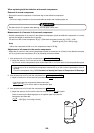
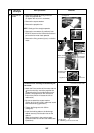
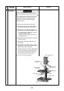
Work procedure
REQUIREMENT
Wear protective clothing on your hands
as other components may cause and
injury etc.
1) Stop the unit operation and turn off the
power supply to the unit.
2) Remove the cables and then the P.C.
board from the board edge spacer at the
corner.
Exchange of service P.C. board
For the interface P.C. board, it is necessary
to set up the jumper links, etc for each
model.
Refer to “Exchange procedure of interface
P.C. board”.
Remarks
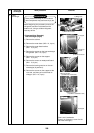
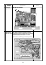
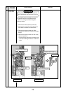
3. IPDU P.C.
board
4. IPDU P.C.
board for fan
1) Stop the unit operation and turn off the
power supply to the unit.
2) Remove the heat sink (Radiator plate)
fixing screws.
∗ (M4 × 16, 2 pcs.)
3) Remove the cables.
4) Remove the P.C. board from the card
edge spacer at the corners.
∗ Heat sink fixing screw, compressor
lead cables (U, V, W), etc, M4 screw
tightening torque (1.47±0.1N•m)
Exchange of service P.C. board
For the IPDU P.C. board, it is necessary to
set up the jumper links, etc for each model.
Refer to “Exchange procedure of IPDU P.C.
board”.
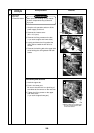
1) Stop the unit operation and turn off the
power supply to the unit.
2) Remove the wires.
3) Remove the heat sink (Radiator plate)
fixing screws.
* (M4 × 8, 4 pcs.)
∗ Tightening torque of screw for heat
sink fixing board (1.47 ± 0.1N•m)