


88
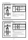
8-3. Check at Main Power-ON
After turning on the main power of the indoor units and outdoor unit in the refrigerant line to be executed with a
test operation, check the following items in outdoor and each indoor unit.
(After turning on the main power, be sure to check in order of indoor unit
→→
→→
→ outdoor unit.)
If the power supply of the outdoor unit has been firstly turned on, [E19] appears on the 7-segment display on
the interface P.C. board until the power supply of the indoor unit is turned on. However it is not an error.
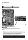
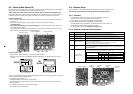
Check on outdoor unit
1. Check that all the rotary switches, SW01, SW02, and SW03 on the interface P.C. board of the outdoor unit
are set up to “1”.
2. If other error code is displayed on 7-segment [B], remove the cause of trouble referring to
“9. Troubleshooting”.
3. Check that [L08] is displayed on 7-segment display [B] on the interface P.C. board of the outdoor unit.
(L08: Indoor address unset up)
(If the address setup operation has already finished in service time, etc, the above check code is not dis-
played, and only [U1] is displayed on 7-segment display [A].)
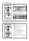
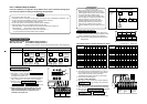
Check on indoor unit
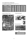
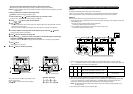
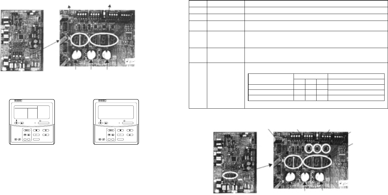
1. Display check on remote controller (In case of wired remote controller)
Check that a frame as shown in the following left figure is displayed on LC display section of the remote
controller.
If a frame is not displayed as shown in the above right figure, the power of the remote controller is not normally
turned on. Therefore check the following items.
• Check power supply of indoor unit.
• Check wiring between indoor unit and remote controller.
• Check whether there is cutoff of cable around the indoor control P.C. board or not, and check connection
failure of connectors.
• Check failure of transformer for the indoor microcomputer.
• Check indoor control P.C. board failure.
Normal status
(Power and operation stop)
GOOD
NO
GOOD
Abnormal status
(Power is not normally turned on.)
ON / OFF
FAN
TEMP.
SWING/FIXTIME
MODE
VENT
UNITSET CL
FILTER
RESET
TEST
TIMER SET
ON / OFF
FAN
TEMP.
SWING/FIXTIME
MODE
VENT
UNITSET CL
FILTER
RESET
TEST
TIMER SET
Interface P.C. board
7-segment display [A]
SW01 SW02 SW03
7-segment display [B]
8-4. Address Setup
After power-ON, set up the indoor address from the interface P.C. board of the outdoor unit.
(The address setup operation cannot be performed by power-ON only.)
8-4-1. Cautions
1. It requires approx. 5 minutes usually for 1 line to automatically set up address.
However in some cases, it may require maximum 10 minutes.
2. It is unnecessary to operate the air conditioner for address setup.
3. Manual address setup is also available besides automatic setup.
Automatic address: Setup from SW15 on the interface P.C. board of the outdoor unit
Manual address: Setup from the weird remote controller.
(For details, refer to section “8-4-3. Address setup procedure”)
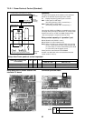
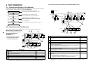
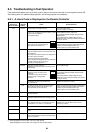
8-4-2. Address Setup and Check Procedure
Procedure
1
2
3
4
5
6
Item
Indoor unit power-ON
Outdoor unit power-ON
7-segment display
check
Address setup start
Display check after
setup
System information
check after setup
Operation and check contents
Turn on power of indoor unit in refrigerant line to which address is set up.
Turn on power of all the outdoor units in refrigerant line to which address is set up.
Check that [L08] is displayed on 7-segment display [B] on the interface P.C. board of the
outdoor unit in the system to which address is set up.
Confirm the corresponding items in “8-4-3 Address setup procedure”, and then set up address
according to the operation procedure.
(Be sure that the setup operation may differ in group control or central control.)
Note) Address cannot be set up if switches are not operated.
• After address setup, [U1] [ ] are displayed in 7-segment display section.
• If an error code is displayed in 7-segment display [B], remove the cause of trouble referring to
“9. Troubleshooting”.
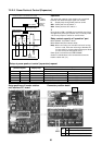
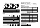
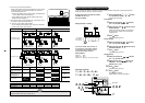
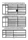
Using 7-segment display function, check the system information of the scheduled system.
(This check is executed on the interface P.C. board of the outdoor unit.)
System capacity
No. of connected outdoor unit
No. of connected indoor units
Rotary switch setup
SW01 SW02 SW03
123
133
143
7-segment display
[A] [B]
[No. of HP] [HP]
[Connected No. of units] [
P]
[Connected No. of units]
After the above checks, return rotary switches SW01, SW02, SW03 to 1/1/1.
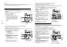
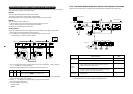
Interface P.C. board
SW01 SW02
Rotary switches
SW03
7-segment
display [A]
Push-switch
SW04
Push-switch
SW05
Push-switch
SW15
7-segment
display [B]