


187
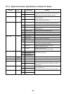
Part type Exchange contents
Initial setup
at shipment
SW01 Rotary SW 4bit 16 step Display / Operation switch (1) For 7-segment display / service operation [1]
SW02 Rotary SW 4bit 16 step Display / Operation switch (2) For 7-segment display / service operation [1]
SW03 Rotary SW 4bit 16 step Display / Operation switch (3) For 7-segment display / service operation [1]
SW04 Push SW For service [Operation/Start] [Operation/Start] by pushing —
SW05 Push SW For service [Stop/End] [Stop/End] by pushing —
Bit 1 Backup setup OFF
Bit 2 Bit 4 Bit 3 Bit 2 Bit 1
(Based on the following setup)
OFF
Bit 3 OFF OFF OFF OFF Normal OFF
Bit 4 ——OFF ON No.1 COMP backup OFF
SW06 SW 4bit
——ON OFF No.2 COMP backup
Bit 1 Power peak-cut control exchange OFF: 0 – 100%, ON: Middle – 100% OFF
Bit 2 Power peak-cut control exchange (Expansion) (For 4-steps exchange) OFF
Bit 3 ——OFF
SW07 SW 4bit
Bit 4 ——OFF
n
Header unit
Bit 1 Outdoor address setup exchange OFF: Auto setup (Normal), ON: Manual setup OFF
Bit 2 Judge indoor capacity over OFF: YES (Normal), ON: NO OFF
Bit 3 Correction of installed pipe size
OFF: Normal, ON: Size UP
(For outdoor expansion)
OFF
SW09 SW 4bit
Bit 4 Judge abnormal No. of connected indoor units OFF: No error judgment, ON: Error OFF
Bit 1 ——OFF
Bit 2 Outdoor fan high-static pressure shift OFF: Normal, ON: High-static pressure shift OFF
Bit 3
OFF: Normal,
ON : INV frequency upper limit restriction
OFF
SW10 SW 4bit
Bit 4
Sound reduction control
OFF: Normal, ON: Fan rpm upper limit restriction OFF
Bit 2 ——OFF
Bit 3 ——OFF
SW11 SW 4bit
Bit 4 Operation when indoor overflow detected
OFF: System stop,
ON : System operation continues
OFF
Bit 1 PMV manual operation selected
OFF: PMV1, PMV2
ON : PMV3
OFF
Bit 2 ——OFF
Bit 3 ——OFF
SW12 SW 4bit
Bit 4 ——OFF
Bit 1 ——OFF
Bit 2 ——OFF
Bit 3 ——OFF
SW13 SW 4bit
Bit 4 Line address setup OFF
SW14 SW 4bit Bit 1, 2, 3, 4 Line address setup Refer to item “Address setup procedure” OFF
SW30 SW 2bit Bit 2 Terminator resistor between outdoor units
OFF: No Terminator resistor
ON : Exists
ON
CN30 Check connector Manual full opening setup of PMV Opened: Normal, Short: Opened fully Open
CN31 Check connector Manual full closing setup of PMV Opened: Normal, Short: Opened fully Open
CN32 Check connector Check for assembly line in factory. Opened: Normal, Short: Check mode Open
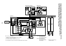
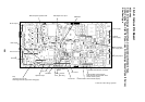
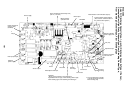
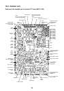
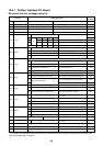
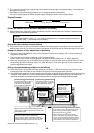
10-2-1. Outdoor Interface P.C. Board
Dip switch function exchange setup list
* The outdoor unit connected with indoor/outdoor communication line becomes automatically the master unit.
No manual setting is necessary.