


223
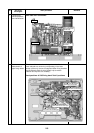
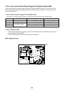
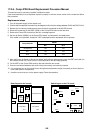
17-2-4. How to Check Fan Power Supply P.C. Board and Fan IPDU
The fan power supply P.C. board supplies DC power. It supplies DC280V for the fan IPDU, and DC12V and
DC7V for the control power supply respectively. If the control power is not supplied, a communication error
(Error code [E31]) is out.
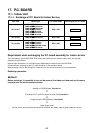
1. How to check fan power supply P.C. board (MCC-1439)
As shown in the following table, measure the voltage of the check positions with a digital tester.
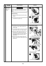
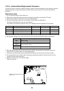
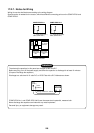
2. How to check fan IPDU
1. Check that the lead wires are correctly inserted into 250 fasten terminal of DC280V input and into the
communication connector (CN01).
2. After then replace the fan IPDU if an abnormality is recognized.
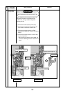
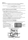
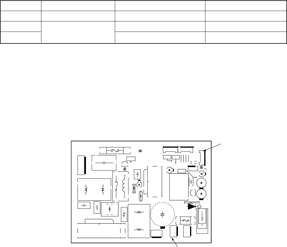
MCC-1439 Front View
15AC
RED
CN510
R523
C522
C521
R511
R518
IC501
1
36
10
IN L500 L506
C513
3CAPA
BLK
CN506
1
3
CN502 BLU
DC IN/OUT
1
31
CN500 WHI
DC OUT
R519
D505
C509
C501
+12V
C520
F500 10A 250V~
+5V
+7V
GND
R505
DB500
+–~~
R503
RY500
L501
F501
T6.3A 250V~
11
C523
C526
C524
R
J505
J503
CN503 WHI
6
11UART
J502
J504
J501
C507
T500
C508
5
6
IC500
J500
G O
IC503
R513
CN505 RED
55131
1
2
UNIT
C520
CN504 BLU UART
+
+
C531
+
+
+
+
CN503
CN500
MCC-1439-05S COMPONENT SIDE
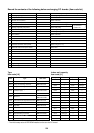
No.
1
2
3
Check item
DC280V output
Control power voltage
Check position
Between CN500
and
Between CN500
and
Between CN500
and
Criteria
DC260 to DC340V
DC12V
DC7V