


207
No.
2
Part to be
exchanged
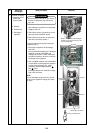
Propeller fan
motor
Work procedure
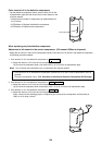
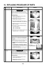
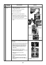
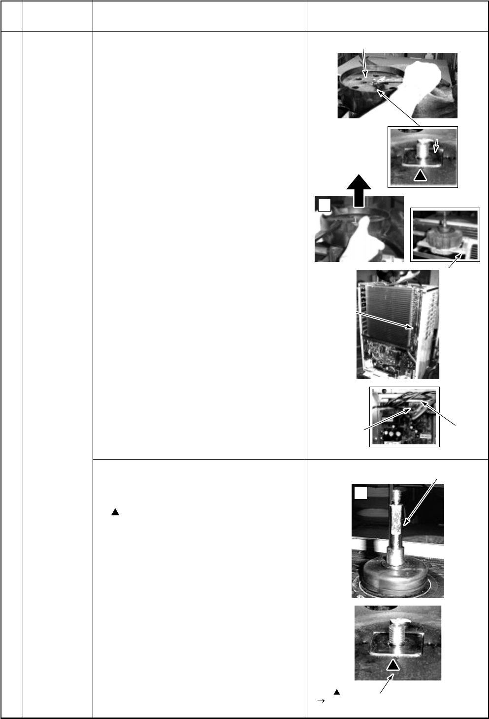
3) Remove the flange nut fixing on the fan
motor and propeller fan.
(To tighten the nut, turn it clockwise.)
4) Remove the square washer.
5) Remove the propeller fan.
NOTE Gently pull the straight upwards.
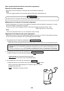
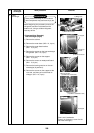
6) Remove the connectors (3 positions) from
IPDU P.C. board on the inverter fan and then
pull out the fan motor lead upwards.
7) Remove the fixing screws (4 pcs.) on the fan
motor.
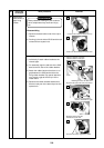
Remarks
M Cautions when exchange/reassembling the
fan motor
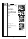
1) Match the D-cut surface of the motor with the
mark on the fan, insert the propeller fan.
(If tightening the D-cut surface when out of
position, the propeller fan will melt due to
friction heat, which will cause the unit to
malfunction.)
2) Be sure to attach the square washer.
(Failure to do so will result in abnormal sound
and vibration being generated.)
3) Tighten the flange nut with 15N•m
(153kg•cm).
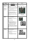
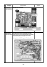
4) Insert the hooking tabs on the discharge
cabinet securely into the tab holes on the
cabinet.
(Refer to the photo in the previous page;
3 positions each at front and rear sides, total
6 positions)
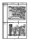
Signal line Power line
Fan mark
Positioning to D-cut face of shaft
D-cut face of motor shaft
3)Flange nut
7)
7)
Scre
Scre
ws
ws
(4 positions)
(4 positions)
Route of the
Route of the
fan motor lead
an motor lead
Route of the
fan motor lead
Remo
Remo
ve the connector
e the connector
and pull it out upw
and pull it out upw
ards
ards
.
Detailed photo
of connector
6)
1)
4)
4)
Square w
Square w
asher
asher
7)Screws
(4 positions)
4)Square washer
Remove the connector
and pull it out upwards.