123
In case of AI-NET central remote controller
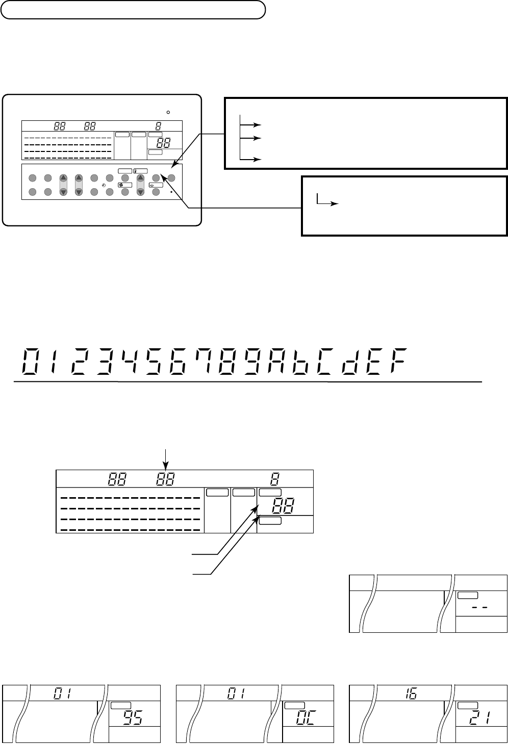
1. Operation for CHECK display
When pushing the CHECK switch, the indoor unit No. (Network address No.) including the check data is
displayed in the UNIT No. display section, and the check code is displayed in the set up temp. display section.
CHECK switch
Push for 0.5 seconds to display CHECK code.
Push for 3 seconds to reset indoor microprocessor.
(While indoor microprocessor is locked by ALL STOP alarm)
Push for 10 seconds to clear check data.
RESET switch
Push the switch in the hole with pin.
The remote controller resets initialized.
(All data is cleared.)
0 1 2 3 4 5 6 7 8 9 10 11 12 13 14 15
(Example)
Hexadecimal
notation
Decimal notation
7 segment display
Display on CHECK monitor
CHECK data
In No.1 unit, first the interconnection wire (bus communication line) of indoor/outdoor has failed.
Next, the room temp. sensor is defective.
For No.16 unit, the high pressure switch at the inverter unit side operates.
(Example)
There is no check data.
Unit line No. (Network address No.)
Check code detected at first
Check code detected at last
FILTER RESET
49 50 5152 53 54 55 56 5758 59 60 61 6263 64
33 34 3536 37 38 39 40 4142 43 44 45 4647 48
17 18 19 20 21 2223 24 25 26 27 2829 30 31 32
1
MONITOR
SET
ZONE
ALL
CENTER
LOCKED
AUX. TYPE
TIMER No.
STANDBY
FILTER
ON
OFF
MODE
FAN ONLY
COOL
DRY
HEAT
AUTO
ON
UNIT
2 3 4 5 6 7 8 9
10 11 1213 14 15 16
FAN
AUTO
HIGH
MED.
LOW
FIX
TEMP.
CHECK
1
2
˚C
LOUVER
MANUAL
LOUVER
FAN
TEMP.
MODE
MONITOR/SET ALL/ZONE
ZONE
UNIT ON
CENTER/LOCKED
CHECK
ZONE SET/ENTER
SELECT
OFF
TIMER ON
49 5051 52 53 5455 56 5758 59 60 6162 63 64
33 3435 36 37 3839 40 4142 43 44 4546 47 48
17 1819 2021 22 2324 25 26 2728 29 3031 32
1
MONITOR
SET
ZONE
ALL
CENTER
LOCKED
AUX. TYPE
TIMER No.
STANDBY
FILTER
ON
OFF
MODE
FAN ONLY
COOL
DRY
HEAT
AUTO
UNIT
2 3 4 5 6 7 8 9
10 1112 13 14 1516
FAN
AUTO
HIGH
MED.
LOW
FIX
TEMP.
CHECK
1
2
˚C
LOUVER
MANUAL
UNIT
TEMP.
CHECK
2
UNIT
TEMP.
CHECK
1
UNIT
TEMP.
CHECK
1
UNIT
TEMP.
CHECK
2. Reading of CHECK monitor display


