


83
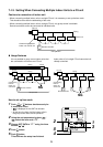
SW07
Bit 1
Bit 2
Operation stop to 60%, 80%, 100%
ON 60% to 60%, 75%, 85%, 100%
Power peak-cut (expansion) ON
OFF
ON
ON
CN513
Blue
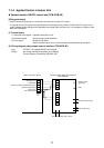
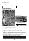
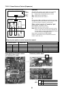
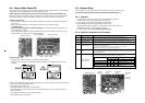
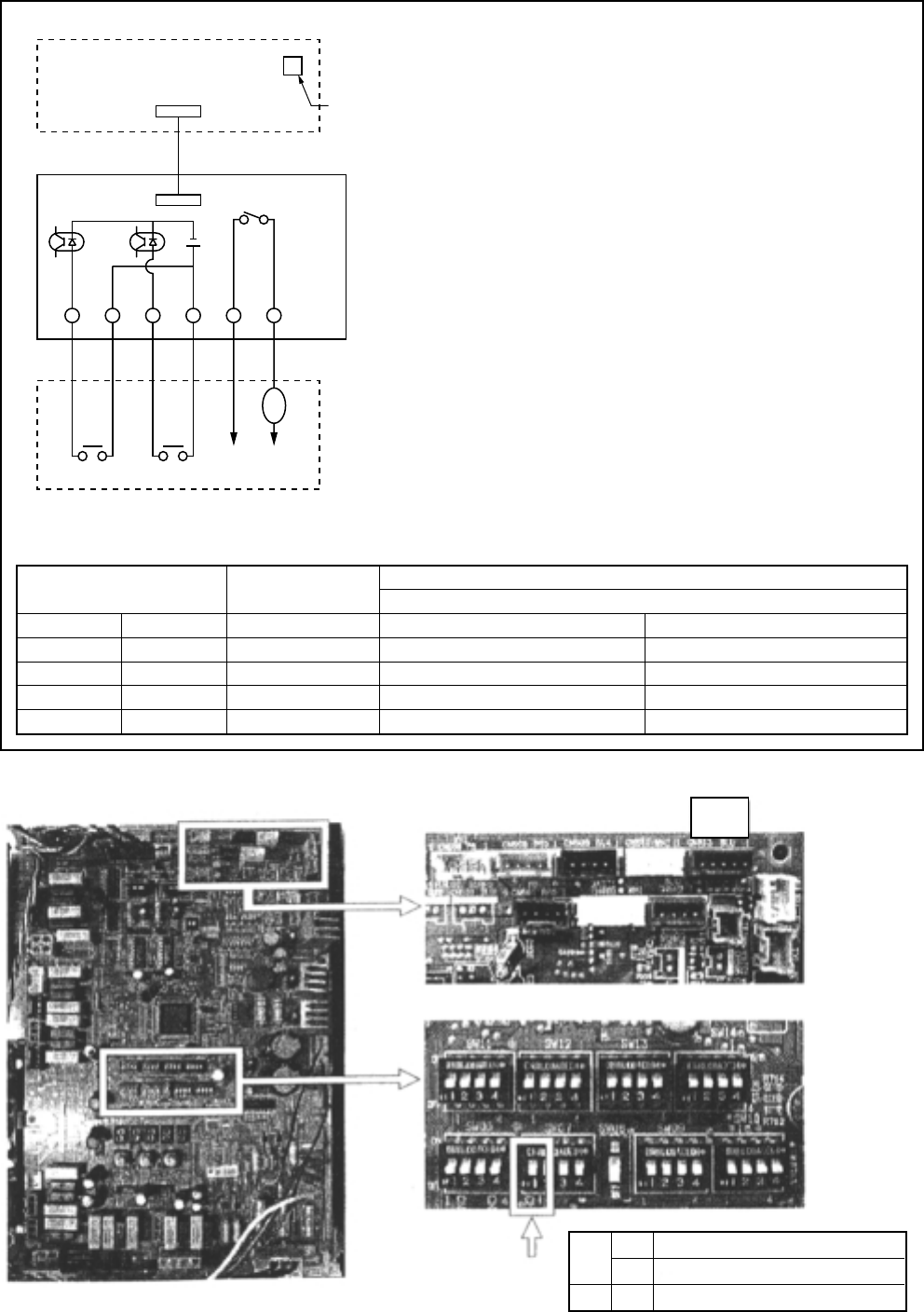
7-2-2-2. Power Peak-cut Control (Expansion)
Setup at power peak-cut control (expansion) request
CN513 (BLU)
Header outdoor unit interface P.C. board
(Setup to
Header
unit only)
SW07
Set up Bit 1.
ON Bit 2.
Connection cable
Power peak-cut
control board
PJ17 (4P WHI)
L1
SW2 SW1
OFF ON
Display
Operation
Power
supply
MAX AC240V
Procured locally
DC
1.2V
Setup positions of header outdoor
unit interface P.C. board
Connector position detail
Switch position detail
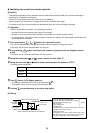
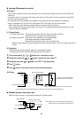
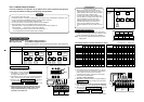
Operation
The upper limit capacity of the outdoor unit is restricted
based on the demand request signal from outside.
L1 : Display lamp during Power peak-cut control
SW1 : Power peak-cut ON switch ∗1
SW2 : Power peak-cut OFF switch ∗1
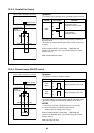
*1
Input signals of SW1 and SW2 are acceptable even if they
are upper than pulse input (100mm. sec.) or serially made.
∗ Be sure to prepare a contact for each terminal.
Relay contact capacity of “operation” port
Below AC240V 1A (COSØ = 100%)
Below DC24V 2A (Non-inductive load)
Note) When connecting non-inductive load such as relay
coil to L1 load, insert the noise surge absorber CR
(In case of AC) or counter electromotive-proof diode
(In case of DC) into the bypass circuit.
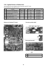
Power peak-cut control board: TCB-PCDM2E
Outdoor unit destination to be connected becomes the
header outdoor unit (U1).
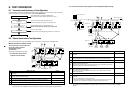
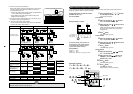
Outside power
peak-cut request
SW1 SW2
OFF OFF
ON OFF
OFF ON
ON ON
Display lamp
L1
OFF
ON
ON
ON
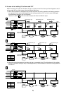
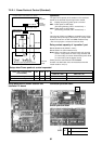
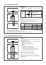
Power Peak-cut request
Outdoor wire interface P.C. board (SW07/ Bit 2 ON)
SW07 : Bit 1 OFF SW07 : Bit 1 ON
100% (Normal operation) 100% (Normal operation)
80% (Upper limit restriction) 85% (Upper limit restriction)
60% (Upper limit restriction) 75% (Upper limit restriction)
0% (Forced stop) 60% (Upper limit restriction)