


117
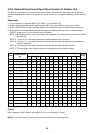
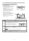
Check code Wireless remote controller
Outdoor 7-segment display
Sensor block display
of receiving unit
Main
remote
controller
display
Auxiliary code
AI-NET central
control display
Operation
Timer Ready
Flash
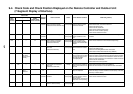
Check code name Detecting device
E01 —— —
¤
ll
Communication error between indoor and remote
controller (Detected at remote controller side)
Remote controller
E02 —— —
¤
ll
Remote controller transmission error Remote controller
E03 —— 97
¤
ll
Communication error between indoor and remote
controller (Detected at indoor side)
Indoor
E04 —— 04
ll
¤
Communication circuit error between indoor/outdoor
(Detected at indoor side)
Indoor
E06 E06
No. of indoor units in which
sensor has been normally
received
04
ll
¤
Decrease of No. of indoor units I/F
— E07 ——
ll
¤
Communication circuit error between indoor/outdoor
(Detected at outdoor side)
I/F
E08 E08 Duplicated indoor addresses 96
¤
ll
Duplicated indoor addresses Indoor / I/F
E09 —— 99
¤
ll
Duplicated main remote controllers Remote controller
E10 —— CF
¤
ll
Communication error between indoor MCU Indoor
E12 E12
01: Indoor/Outdoor
communication
02: Communication between
outdoor units
42
¤
ll
Automatic address start error I/F
E15 E15 — 42
ll
¤
Indoor is nothing during automatic addressing I/F
E16 E16
00: Capacity over
01 ~: No. of connected units
89
ll
¤
Capacity over / No. of connected indoor units I/F
E18 —— 97, 99
¤
ll
Communication error between indoor units Indoor
E19 E19
00: Header is nothing
02: Two or more header units
96
ll
¤
Outdoor header units quantity error I/F
E20 E20
01: Outdoor of other line
connected
02: Indoor of other line
connected
42
ll
¤
Other line connected during automatic address I/F
E23 E23 — 15
ll
¤
Sending error in communication between outdoor units I/F
E25 E25 — 15
ll
¤
Duplicated follower outdoor addresses I/F
E26 E26
No. of outdoor units which
received signal normally
15
ll
¤
Decrease of No. of connected outdoor units I/F
E28 E28 Detected outdoor unit number d2
ll
¤
Follower outdoor unit error I/F
E31 E31
01: IPDU1 error
02: IPDU2 error
03: IPDU1, 2 error
04: Fan IPDU error
05: IPDU + Fan IPDU error
06: IPDU2 + Fan IPDU error
07: All IPDU error
CF
ll
¤
IPDU communication error I/F
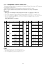
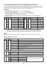
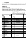
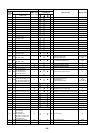
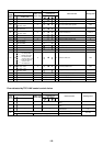
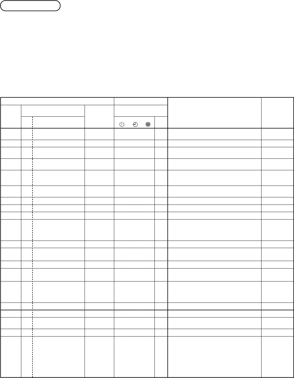
9-2. Check Method
If an trouble occurs, the error code can be retrieved from the main remote controller/central remote controller (LCD
display) or the header unit interface P.C. board (7-segment display). Using this self diagnostic function, the trouble
can be identified using the table below.
Check code list
The following list shows all fault codes.
• If check code is from indoor remote controller: See “Main remote controller display” in the list.
• If check code is from outdoor unit: See “Outdoor 7-segment display” in the list.
• If check code is from AI-NET central control remote controller: See “AI-NET central control display” in the list.
• If check code is from indoor unit with wireless remote controller: See “Sensor display of receiving unit” in the list.
IPDU: Intelligent Power Drive Unit
¡ : Lighting,
¤
: Flashing,
l
: Goes off
ALT.: Flashing is alternately when there are two flashing LED.
SIM: Simultaneous flashing when there are two flashing LED