


20
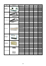
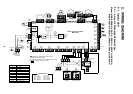
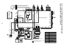
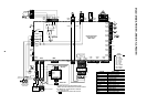
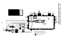
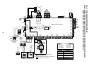
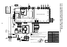
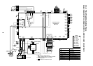
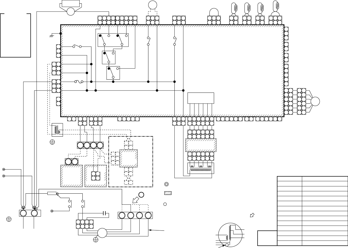
2-1-6. Concealed Duct High Static Pressure Type
Model: MMD-AP0181H, AP0241H, AP0271H, AP0361H, AP0481H
TC1
TC2
CN080
(GRN)
CN101
(BLK)
CN073
(RED)
CN070
(WHI)
4 2
5 4 3 2 1
9 8 7 6
9 8 7 6
FAN
CN083
(WHI)
DP
(BLU)
CN068
DP
CN304
(GRY)
CN066
(WHI)
CN067
(BLK)
(BLK)
PNL
EXCT
1
2
1
2
Filter
CN082
(BLU)
CN060
(WHI)
Option
CN032
(WHI)
CN075
(WHI)
CN074
(WHI)
TR
T10
1
2
6
5
4
3
2
1
6
5
4
3
2
1
5
2
1
3
4
6
5
2
1
3
4
6
CN081
(BLK)
1
2
3
4
5
3
1 2 3 4 5 6
CN061
(YEL)
Fan drive
1 2 3 4 5 61 2 3 4 5 6
1 2 3
1 2 3
1 3
1 21 2
1 2
1 2 3
1 2 3
1 2 3
1 2 3
4 5 6
CN050
(WHI)
CN041
(BLU)
CN040
(BLU)
CN044
(BRW)
1 2
1 2 3 4 5
RY004
P301
1
2
3
1
2
RY002
RY006
RY007
RY005
1 2
BA
S(N)R(L)
U2
1 2
Remote controller
CN1
(WHI)
Power supply
Single phase
220-240V 50Hz
220V 60Hz
Indoor unit
Earth screw
Outdoor unit
U1
U2U1
Power
supply
circuit
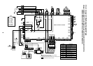
Symbol
FM
RC
TR
TA
TC1,TC2,TCJ
RY005~007
RY001
RY002
PMV
F
43F1
DM
FS
Parts name
Fan motor
Running capacitor
Transformer
Indoor temp sensor
Temp sensor
Fan motor control relay
Louver motor control relay
Drain control relay
Pulse Motor Valve
Fuse
Fan motor control relay
Drain pump motor
Float switch
Sold
separately
LM
(GRN)
CN033
1 2 3
1 2 3
CN100
(BRN)
1 2 3
1 2 3
1 2 3
1 2 3
1 2
1 2
TCJ
CN102
(RED)
1 2
1 2
TA
CN104
(YEL)
FS
CN030
(RED)
1 2
1 2
RY001
TR
OC
EMG
RC
Fuse
T5.0A
T10A,250V~
1
2
3
1
2
3
CN309
(YEL)
1
2
3
1
2
3
REDWHI
HML UL
1. indicates the terminal block, letter at inside indicates the terminal number.
2. A dotted line and broken line indicate the wiring at site.
3. indicates the control P.C. board.
4. When attaching a drain pump, exchange CN030 connector with the connector
of the float switch.
5. A part is connected to the terminal block.
When exchanging to the outside static pressure necessary at the local site,
check the terminal No. and lead color of the fan motor in the below diagram,
and then exchange the lead wire indicated by the arrow mark ( ).
PMV
(Option)
CN01
(WHI)
CN02
(BLU)
WHI
A
WHI
RED
GRY
WHI
RED
BLU
ORN
BLK
BRN
GRY
YEL
RED
REDRED F
RED
WHI
43F1
6
4
CN03
(RED)
MCC-1401
Network adaptor
(Option)
1 2
1 2
1 2
1 2
X Y
3 3
2
1 1
43F1
Spark
killer
87
43F1
5
3
1 2 3 4
1 2 3 4
F1 F2 F3 F4
RC
FM
WHI
BLK
BLU
ORN
BRN
GRY
RED
49F
Indoor control P.C. board
Closed
end
connector
Closed end
connector
Wired for MMD-AP0481 only
(BRN Wire)
Motor over heating protection switch
Color
indication
RED : RED
WHI : WHITE
YEL : YELLOW
BLU : BLUE
BLK : BLACK
GRY : GRAY
PNK : PINK
ORN : ORANGE
BRW : BROWN
GRN : GREEN
1 2 3 4 5 6
1 2 3 4 5 6
1 2 3 4 5 6
1 2 3 4 5 6
CN01
(WHI)
CN02
(YEL)
Sub P.C. board
MCC-1520
Flow selector
unit earth
screw