


226
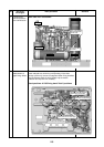
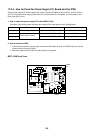
17-2-7. Notice for Wiring
Wiring for service shall be done according to the wiring diagram.
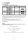
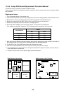
Special caution is needed for the reactor, which has different connecting points on the COMP-IPDU1 and
COMP-IPDU2.
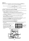
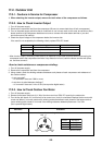
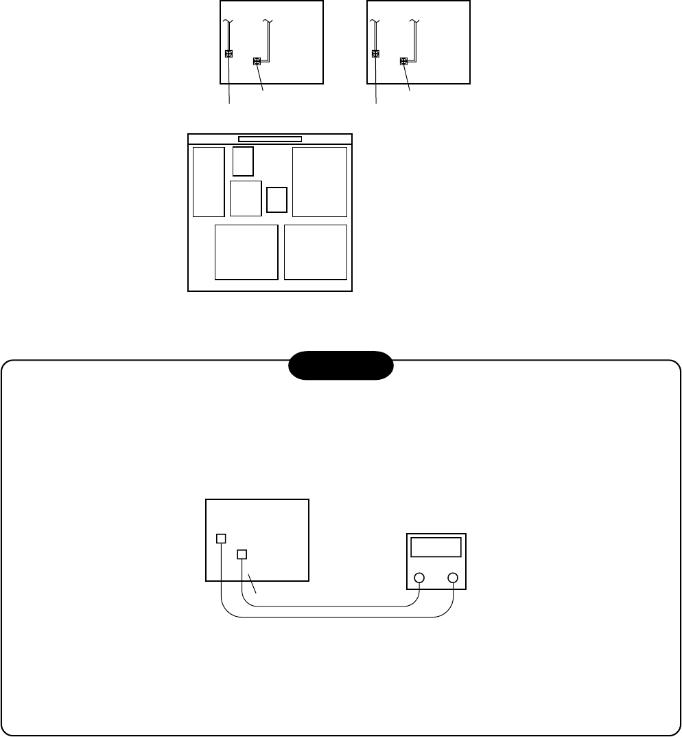
DANGER
The electrolytic capacitors in this panel are charged to 660 volts D.C.
Before servicing, turn off the power supply and allow the capacitor to discharge for at least 10 minutes.
(Purpose: Discharge the capacitor)
Discharge to a safe level of 10 volts D.C. or LESS. Test with a D.C. Voltmeter as shown.
TO REACTOR 1
COMP-IPDU No.1
CN20 (REACTOR 1)
CN21 (REACTOR 1)
TO REACTOR 2
COMP-IPDU No.2
CN08 (REACTOR 2)
CN07 (REACTOR 2)
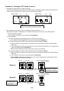
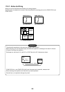
P.C.
board
noise
filter
P.C.
board
power
P.C. board
interface
P.C. board
Comp-IPDU
No.2
P.C. board
Comp-IPDU
No.1
Inverter front view
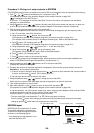
10V, DC
CN13
(CAPA–)
CN15
(CAPA+)
Comp-IPDU No.1 & No.2
COMP-IPDU No. 1 and COMP-IPDU No.2 have the same electric potential, measure both.
Never discharge the capacitor terminals with any metal implement.
Personal injury or equipment damage may result.