


196
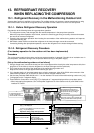
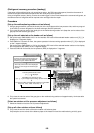
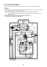
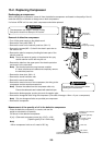
Capillary tube
Capillary
tube
Capillary
tube
Capillary
tube
FM
Propeller fan
Fan motor
Sensor
(TO)
Sensor
(TS1)
Sensor
(TS2)
Sensor
(TL)
Sensor
(TE1)
(Right side)
Main heat exchanger
Solenoid valve
(SV2)
Solenoid valve
(SV12)
Solenoid valve
(SV41)
Solenoid
valve
(SV3A)
Solenoid
valve
(SV3E)
Solenoid
valve
(SV3B)
Solenoid valve
(SV3D)
Solenoid
valve
(SV6)
Solenoid
valve
(SV5)
Solenoid
valve
(SV11)
Solenoid
valve
(SV3C)
4-Way valve
Check
joint
Low-
pressure
sensor
Accumulator
Check joint
Check
joint
High-pressure
sensor
High-
pressure
switch
High-
pressure
switch
Oil
separator
Check
valve
Check
valve
Check
valve
Check
valve
Strainer
Sensor
(TK1)
Sensor
(TK4)
Sensor
(TK3)
Capillary tube
Capillary tube
Strainer
Capillary tube
Strainer
Strainer
Strainer
Strainer Strainer
Capillary
tube
Capillary tube
Solenoid valve
(SV42)
Check
valve
Check
valve
Capillary
tube
Check
valve
Compressor 2
(Inverter)
Compressor 1
(Inverter)
Strainer Strainer
Sensor
(TK2)
Sensor
(TD2)
Sensor
(TD1)
Liquid
tank
Oil tank
Service
valve of
balance
pipe
Service
valve at
liquid
side
Service
valve at
discharge
gas side
Service
valve at
suction
gas side
Pulse motor valve
(Left side)
Main heat exchanger
(PMV1) (PMV2)
(PMV3)
Check
valve
Strainer
Check
valve
Sub heat exchanger (Right side)
Sub
heat exchanger (Left side)
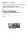
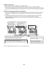
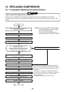
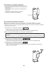
13-3. Process after Repair
After completion of the repair work, perform vacuuming of the outdoor unit using the following procedure.
Procedure
1. Short CN30 on the interface P.C. board on the outdoor unit for which the repair work has been completed, to
open the PMV fully. (Confirm that Bit 1 of SW12 is OFF.)
Note) The PMV opening by using short CN30 returns the PMV to fully closed after 2 minutes.
To continue to fully open status, turn off the power supply of the outdoor unit within 2 minutes after
using short CN30.
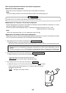
2. Be sure to perform vacuuming from the following three check joints.
(Liquid pipe, discharge pipe, and suction pipe)