


175
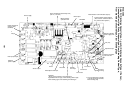
Display
LCD
Function setup
Display
LED
CPU
Remote
controller
communication
circuit
Remote
controller
communication
circuit
CPU
H8/3039
Driver
Remote
controller
communication
circuit
Key switch
Power
circuit
Power
circuit
Transformer
Transformer
Switch
setup
DC5V
Display
LCD
LCD
driver
Function setup
CPU
Key switch
Power
circuit
Secondary
battery
DC5V
*
3
Same
as left
*2
CN2 CN1
#2
AB
L
U1 U2
N
L
AB
NU1 U2
U1 U2
Power
supply
Outdoor
unit
Same
as left
*2
#3
AB
L
U1 U2
N
Power
supply
Outdoor
unit
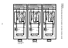
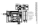
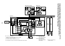
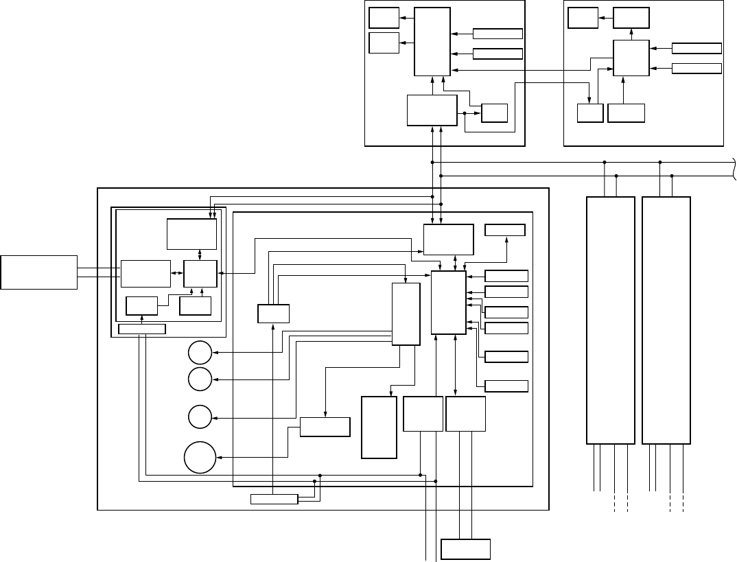
Network adaptor (Option)
Indoor unit
#1
Central control
remote controller
(Option)
X
Y
(In case of AI-NETWORK)
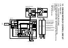
Network
adaptor
P.C. board
(MCC-1401)
Indoor control P.C. board (MCC-1403)
DC5V
DC20V
DC12V
DC5V
AI-NET
communication
circuit
CPU
H8/3687
PMV
Louver
motor
Drain
pump
Indoor
fan motor
EEPROM
TA sensor
TCI sensor
TC2 sensor
TCJ sensor
Float input
HA
BUS
communication
circuit
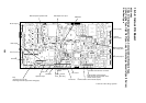
Outdoor unit
Power supply
1Ø220-240V, 50Hz
AC
synchronous
signal input
circuit
Fan motor
control circuit
Start
Alarm
Ready
Thermostat ON
COOL
HEAT
FAN
Indoor/Outdoor
communication
Outside
output
Power
circuit
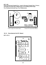
Max. 8 units are connectable. *1
*1 However in a case that the network
adaptor is installed when 2 remote
controllers are connected,
maximum 7 units are connectable.
*2 The network adaptor is installed to only
one unit.
*3 The weekly timer cannot be connected
to the simple wired remote controller.
*4 Nome for concealed duct,
Floor standing cabinet
Floor standing concealed
*5 Nome for concealed duct,
Floor standing cabinet
Floor standing concealed
Floor standing
*6 Nome for 1-way discharge
cassette YH type.
Wired remote controller
(Up to 2 units)
Weekly timer
None for
Concealed Duct
*
4
*
5
*
6
*
5
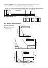
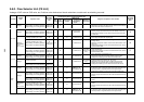
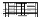
2-way Air Discharge Cassette Type, 1-way Air Discharge Cassette Type (1 Series),
Concealed Duct High Static Pressure Type, Floor Standing Cabinet Type,
Floor Standing Concealed Type, Floor Standing Type