


22
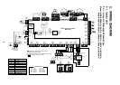
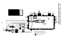
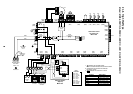
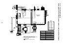
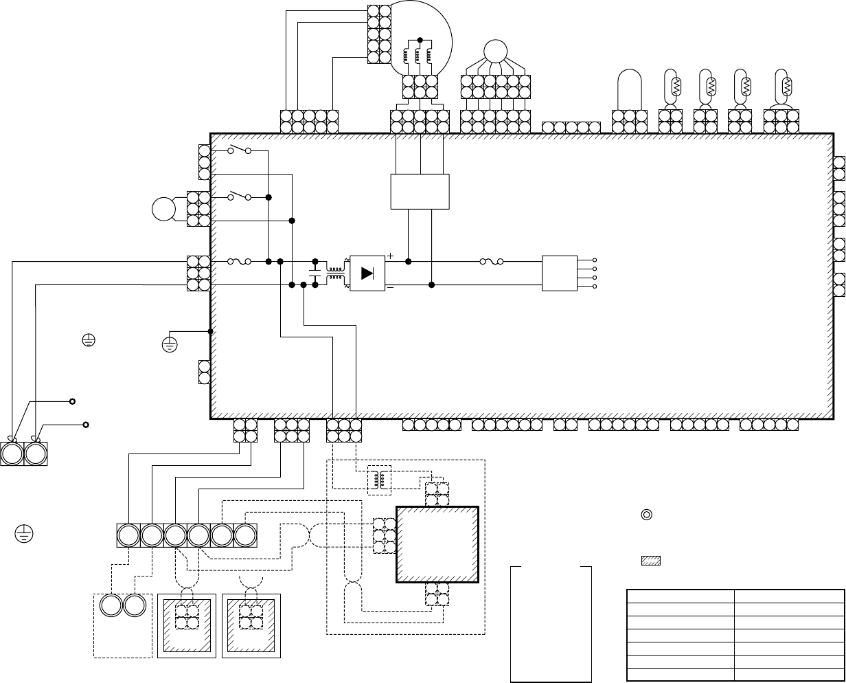
2-1-8. High Wall Type
Model: MMK-AP0071H, AP0091H, AP0121H, AP0151H, AP0181H, AP0241H
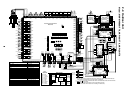
FM
TA
TC1,TC2,TCJ
PMV
LM
RY303
Fan motor
Indoor temp sensor
Temp sensor
Pulse motor valve
Louver motor
Louver control relay
Symbol
Parts name
Color
indication
RED : RED
WHI : WHITE
YEL : YELLOW
BLU : BLUE
BLK : BLACK
GRY : GRAY
PNK : PINK
ORN : ORANGE
BRW : BROWN
GRN : GREEN
1. indicates the terminal bolock.
Letter at inside indicates the terminal number.
2. A dotted line and broken line indicate
the wiring at side.
3. indicates the control P.C. board.
CN080
(GRN)
EXCT
2
3
1
CN68
(BLU)
3
1
CN304
(GRY)
3
1
3
1
CN67
(BLK)
CN66
(WHI)
3
1
2
1
3
1
CN103
(GRN)
2
1
CN73
(RED)
2
1
CN70
(WHI)
2
1
1
1
2 31 2 3 4 5
3
CN100
(BRW)
CN101
(BLK)
CN34
(RED)
CN33
(WHI)
1 2 3 4 5
CN20
(BLU)
1 2 3 4 5
CN81
(BLK)
1 2 3 4 5 6
CN60
(WHI)
1 2 3 4 5
6
CN61
(YEL)
1 2 31 3
1 3
1 21 2
1 2
3
1 3
4 5
CN50
(WHI)
CN41
(BLU)
CN40
(BLU)
GRY
BLU
BLU
BLK
BLK
BLK
WHI
GRY
CN309
(YEL)
Option
1 2
CN32
(WHI)
Fandrive
CN82
(BLU)
Motor drive
circuit
CN333
(WHI)
CN334
(WHI)
TC1
TC2
CN102
(RED)
TCJ
2
1
2
1
2
1
2
1
2
1
2
1
CN104
(YEL)
TA
1
1
3
3
1 2 3 4 5 6
1
1
1 2 3 4 5 6
1 234 56
1 234 56
2
2
34
4
5
5
1 3 5
1 3
1 2 3
1 2 3
5
PMV
11
5
4
5
4
LM
P301
BLK
RY302
FUSE
T6.3A 250V~
RY303
1
1
2
2
1
1
2
2
3
2
1 1
3
CN01(WHI)
CN03(RED)
CN02
(BLU)
TR
1
1
2
2
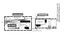
Network adaptor
(Option)
MCC-1401
U1 U2
U1 U2
A B X Y
CN1
(WHI)
WHI BLK
Wired remote
controller
Outdoor
unit
1
1
2
2
CN001
(WHI)
WHI BLK
Adaptor for
wireless remote
controller
Power supply
single phase
220-240V 50Hz
220V 60Hz
Indoor unit
Earth screw
Closed-end
connector
RED
WHI
R(L) S(N)
FM
FUSE
T3.15A 250V~
Power
supply
circuit
DC20V
DC15V
DC12V
DC7V
Control P.C. board
for Indoor unit
MCC-1402
Flow selector
unit earth
screw
RED
WHI