


225
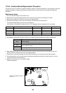
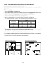
17-2-6. Comp-IPDU Board Replacement Procedure Manual
This service board is commonly installed in different models.
If the board assembly is to be replaced, replace it properly in with the correct version for the model and follow
this procedure.
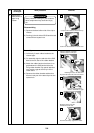
Replacement steps
1. Turn off the power supply to the outdoor unit.
2. Confirm that the capacitor has been fully discharged (confirm that the voltage between CN13 and CN15 is 0 V).
3. Remove the connectors, fasteners and screw terminals connected to the A3-IPDU board.
4. Remove 2 screws that fix the IGBT (Q200) of the Comp-IPDU board to the heat sink.
5. Remove the Comp-IPDU board from the four card edge spacers.
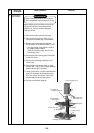
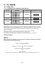
6. Set the dip Switch (SW801) of the Comp-IPDU board, as instructed in the table below.
If the model is not specified, inspection “L29” is displayed and the equipment will not operate.
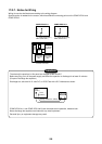
7. After setting the dip Switch of the service board, apply silicone grease evenly onto the IGBT and install it in
the outdoor control unit (Confirm that it is securely fixed to the card edge spacers).
8. Fix the IGBT of the Comp-IPDU board to the heat sink with two screws.
9. Connect connectors/fasteners and confirm they are correctly and securely inserted.
10. If a component part on the board is bent during board replacement, adjust it manually so that it does not
touch other parts or components.
11. Install the cover then turn on the power supply. Check the operation.
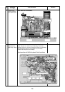
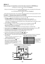
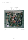
Noise
filter
board
Terminal
Power
supply
P.C. board
assembly
Interface board
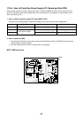
Board layout of the inverter
Comp-IPDU
No.1
Comp-IPDU
No.2
Magnetic
switch
Fan IPDU
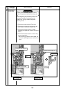
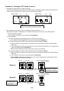
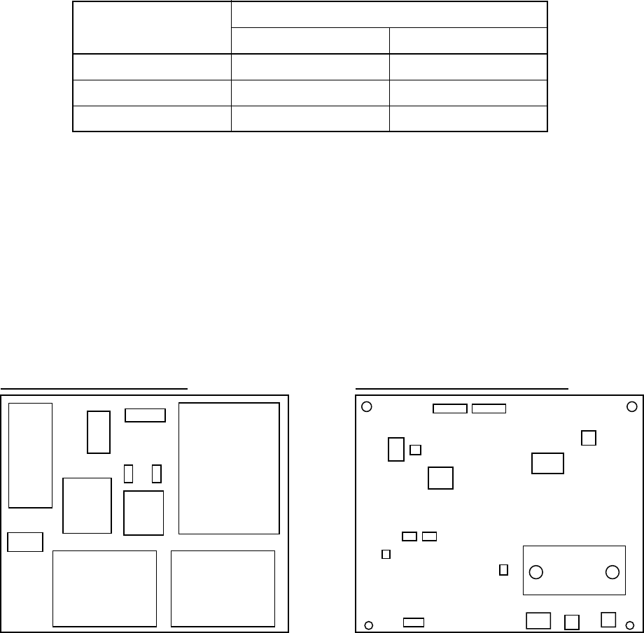
Switch layout on the P.C. board
Q200
IC101
IC222
SW801
T01
T03
CN26
T05
CN15
CN13
CN17
T04T02
Comp-IPDU No.
JAt shipment
No.1
No.2
SW801
Bit 1 Bit 2
ON ON
ON ON
ON OFF