


89
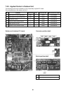
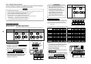
8-4-3. Address Setup Procedure
In this air conditioner, it is required to set up address to the indoor unit before starting opera-
tion. Set up the address according to the following setup procedure.
CAUTION
1. Set up address after wiring work.
2. It requires maximum 10 minutes (Usually, approx. 5 minutes) to set up automatically an address to 1 line.
3. To set up an address automatically, the setup at outdoor side is necessary.
(Address setup cannot be performed by power-ON only.)
4. To set up an address, it is unnecessary to operate the air conditioner.
5. Manual address setup is also available besides automatic setup.
Automatic address : Setup from SW15 on the interface P.C. board of the header unit
Manual address : Setup from the wired remote controller
∗ It is temporarily necessary to set the indoor unit and wired to 1 : 1.
(In group operation and in time without remote controller)
Automatic Address Setup
Without central control : To the address setup procedure 1
With central control : To the address setup procedure 2
(However, go to the procedure 1 when the central control is performed in a single refrigerant line.)
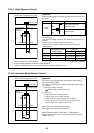
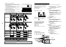
(Example)
Address setup procedure
Cable systematic diagram
In case of central control in a single refrigerant line
To procedure 1
In case of central control over refrigerant lines
To procedure 2
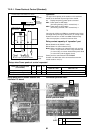
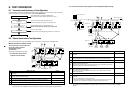
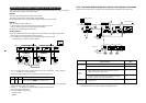
Address setup procedure 1
1. Turn on power of indoor/outdoor units.
(In order of indoor
→→
→→
→ Outdoor)
2.
After approx. 1 minute, check that U. 1. L08 (U. 1. flash)
is displayed in 7-segment display section on the interface
P.C. board of the outdoor unit.
3. Push SW15 to start the setup of the automatic addressing.
(Max. 10 minutes for 1 line (Usually, approx. 5 minutes))
4.
When the count Auto 1 → Auto 2 → Auto 3 is displayed
in 7-segment display section, and it changes from
U. 1. - - - (U. 1. flash) to U. 1. - - - (U. 1. light) , the setup
finished.
5. When performing an automatic address setup on a
single refrigerant line with central control, connect
relay connected between [U1, U2] and [U3, U4]
terminals in the header unit.
SW04
SW01
111
SW05 SW15
D600 D601 D602 D603 D604
SW02 SW03
3
5
2, 4
Header unit interface P.C. board
U1 U2
For internal
wiring between
indoor and
outdoor
U3 U4
For wiring of
central control
system
U5 U6
For internal
wiring between
outdoor units
Outdoor
Indoor Indoor
Remote
controller
Remote
controller
Central
remote controller
Outdoor
Indoor Indoor
Remote
controller
Central
remote controller
Outdoor
Indoor Indoor
Remote
controller
Remote
controller
Outdoor
Indoor Indoor
Remote
controller
Central
remote controller
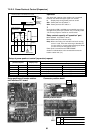
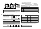
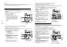
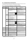
REQUIREMENT
• When a group control is performed over the
multiple refrigerant lines, be sure to turn on the
power supplies of all the indoor units connected
in a group at the time of address setup.
• If turning on the power for each refrigerant line
to set up address, a header indoor unit is set for
each line. Therefore, an alarm code “L03”
(Duplicated header indoor units) is output in
operation after address setup. In this case,
change the group address from the wired
remote controller for only one header unit is set
up.
(Example)
Cabling
systematic
diagram
Group control over
multiple refrigerant lines
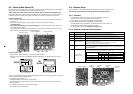
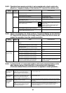
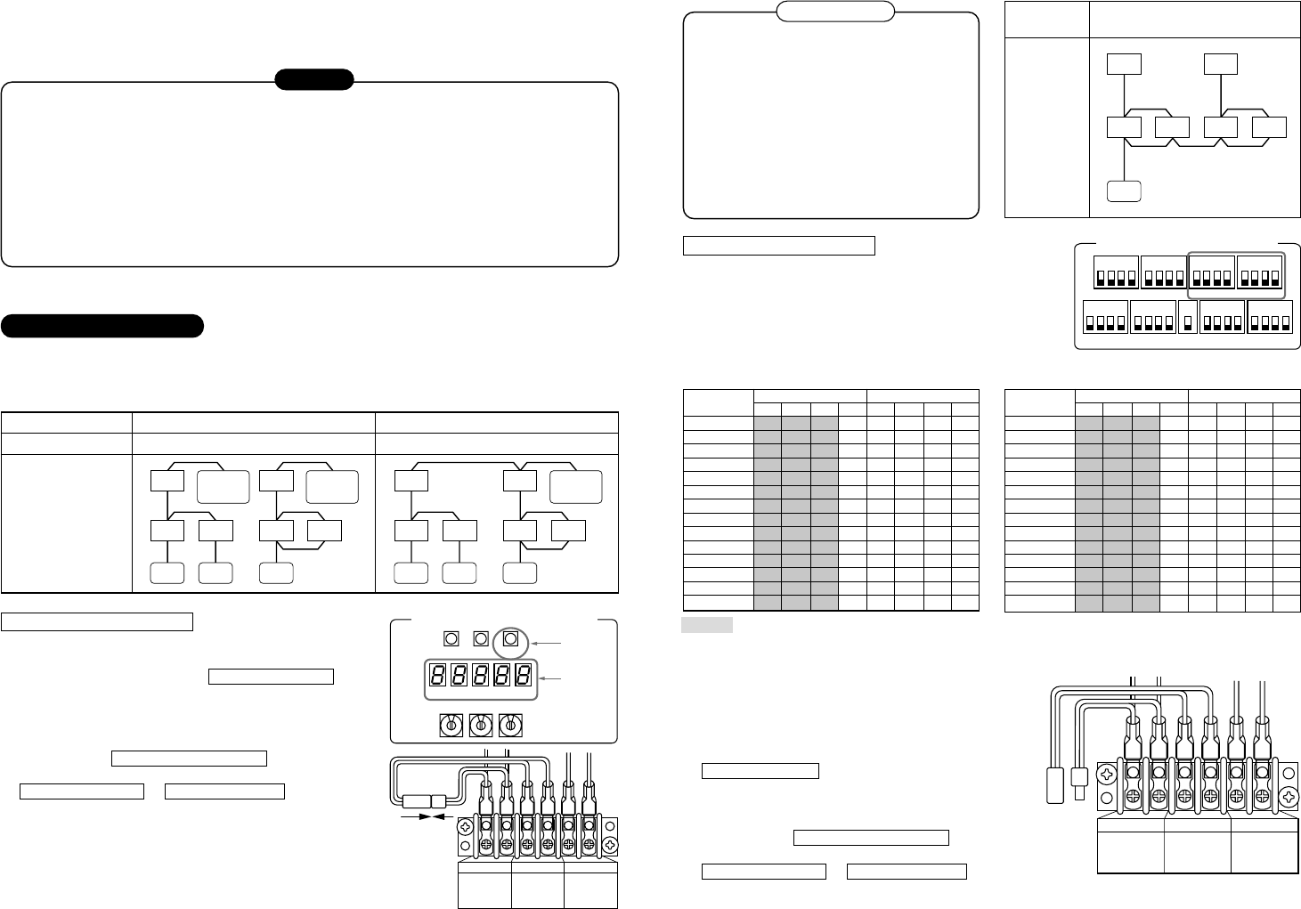
Address setup procedure 2
1. Using SW13 and 14 on the interface P.C. board of the
outdoor unit in each system, set up the address for each
system. (At shipment from factory: Set to Address 1)
Note) Be careful not to duplicate addresses with the other
refrigerant line.
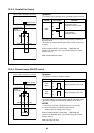
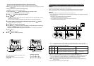
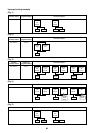
Line address switch on outdoor interface P.C. board (¡: Switch ON, × : Switch OFF)
2. Check that the relay connectors between [U1, U2] and
[U3, U4] terminals are not connected in all the outdoor
units to which the central control is connected.
(At shipment from factory: Connector not connected)
3. Turn on power of indoor/outdoor.
(In order of indoor
→→
→→
→ outdoor)
4. After approx. 1 minute, check that 7-segment display is
U.1.L08 (U.1. flash) on the interface P.C. board of the
outdoor unit.
5. Push SW15 to start the setup of automatic addressing.
(Max. 10 minutes for 1 line (Usually, approx. 5 minutes))
6.
When the count Auto 1
→→
→→
→ Auto 2
→→
→→
→ Auto 3 is displayed
in 7-segment display section, and it changes from
U. 1. - - - (U. 1. flash) to U. 1. - - - (U. 1. light) , the
setup finished.
7. Procedure 4. to 6. are repeated in other refrigerant lines.
: Is not used for setup of system address. (Do not change setup.)
Outdoor
Indoor Indoor
Remote
controller
Outdoor
Indoor Indoor
SW11
1
ON
Header unit interface P.C. board
2 3 4
SW12
1
ON
2 3 4
SW06
1
ON
2 3 4
SW07
1
ON ONON ON
2 3 4
SW09SW08
11 2 3 4
SW10
1 2 3 4
SW13
1
ON
2 3 4
SW14
1
ON
2 3 4
U1 U2
For internal
wiring between
indoor and
outdoor
U3 U4
For wiring of
central control
system
U5 U6
2
For internal
wiring between
outdoor units
Line
address
1
2
3
4
5
6
7
8
9
10
11
12
13
14
SW13 SW14
12341234
×××××
×
¡
×××
××
¡
××
×
¡¡
××
×××
¡
×
×
¡
×
¡
×
××
¡¡
×
×
¡¡¡
×
××××
¡
×
¡
××
¡
××
¡
×
¡
×
¡¡
×
¡
×××
¡¡
×
¡
×
¡¡
Line
address
15
16
17
18
19
20
21
22
23
24
25
26
27
28
SW13 SW14
12341234
××
¡¡¡
×
¡¡¡¡
¡
××××
¡¡
×××
¡
×
¡
××
¡¡¡
××
¡
××
¡
×
¡¡
×
¡
×
¡
×
¡¡
×
¡¡¡¡
×
¡
×××
¡
¡¡
××
¡
¡
×
¡
×
¡
¡¡¡
×
¡