


102
8-7. Service Support Function
8-7-1. Function to Start/Stop (ON/OFF) Indoor Unit from Outdoor Unit
The following functions enables the start and stop of the indoor units using the switches on the interface P.C.
board of the header unit.
NOTE 1) This start/stop function only sends
the command signals from the
outdoor unit to the indoor unit, such
as start, stop, operation mode, etc.
Once it does not resend the signals
even if the indoor unit does not follow
the sent signals.
NOTE 2) The above controls are not available
when an error has caused the system
to stop.
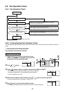
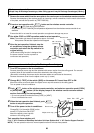
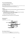
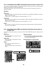
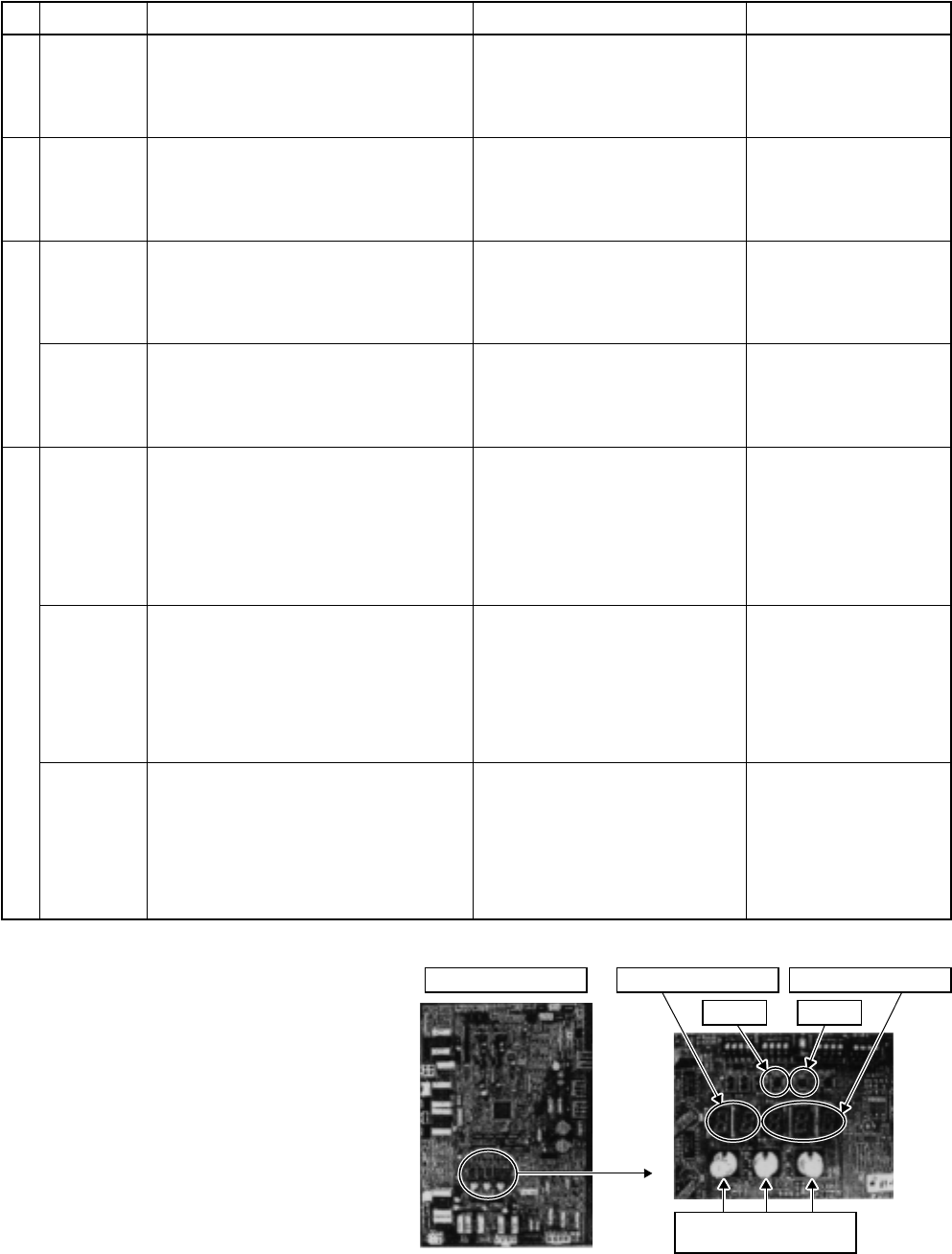
Interface P.C. board
7-segment display [A] 7-segment display [B]
SW04 SW05
SW01 SW02 SW03
Rotary switch
No.
1
2
3
4
Function
All cooling
test operation
All heating
test operation
Batch start
Batch stop
Individual
start
Individual
stop
Individual test
operation
Outline
Changes the mode of all the connected indoor
units collectively to cooling test operation.
Note) Control operation same as test
operation for remote controller.
Changes the mode of all the connected indoor
units collectively to heating test operation.
Note) Control operation same as test
operation for remote controller.
Starts all the connected indoor units collec-
tively.
Note) The contents follow the setup of remote
controller.
Stops all the connected indoor units collec-
tively.
Starts the specified indoor unit.
Notes)
• Control operation same as test.
• The other indoor units keep existing status.
Stops the specified indoor unit.
Note) The other indoor units keep existing
status.
Operates the specified indoor unit.
Note) The other indoor units keep existing
status.
Setup/Release
[Setup]
Push SW04 for 2 seconds or more
with SW01”2”, SW02”5”, SW03”1”.
[Release]
Return SW01, SW02, SW03 to “1”.
[Setup]
Push SW04 for 2 seconds or more
with SW01”2”, SW02”6”, SW03”1”.
[Release]
Return SW01, SW02, SW03 to “1”.
[Setup]
Push SW04 for 2 seconds or more
with SW01”2”, SW02”7”, SW03”1”.
[Release]
Return SW01, SW02, SW03 to “1”.
[Setup]
Push SW05 for 2 seconds or more
with SW01”2”, SW02”7”, SW03”1”.
[Release]
Return SW01, SW02, SW03 to “1”.
[Setup]
Push SW04 for 2 seconds or more set
SW01 “16” and set SW02 and SW03
to address No. (1 to 64) to be started.
[Release]
Return SW01, SW02, SW03 to “1”.
[Setup]
Push SW05 for 2 seconds or more set
SW01 “16” and set SW02 and SW03
to address No. (1 to 64) to be stopped.
[Release]
Return SW01, SW02, SW03 to “1”.
[Setup]
Push SW04 for 10 seconds or more
set SW01 “16” and set SW02 and
SW03 to address No. (1 to 64) to be
operated.
[Release]
Return SW01, SW02, SW03 to “1”.
7-segment display
Section A Section B
[C ] [ –C]
Section A Section B
[H ] [ –H]
Section A Section B
[CH] [ 11]
[ 11] is displayed on
Section B for 5 seconds.
Section A Section B
[CH] [ 00]
[ 00] is displayed on
Section B for 5 seconds.
Section A Section B
[ ] [ ]
Section A:
Displays the corresponding
indoor address.
Section B:
Displays [ 11] for 5 seconds
from operation-ON.
Section A Section B
[ ] [ ]
Section A:
Displays the corresponding
indoor address.
Section B:
Displays [ 00] for 5 seconds
from operation-OFF.
Section A Section B
[ ] [ ]
Section A:
Displays the corresponding
indoor address.
Section B:
Displays [ FF] for 5 seconds
from test operation-ON.