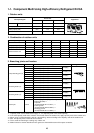
93
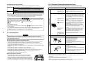
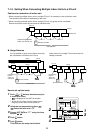
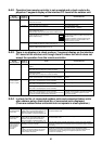
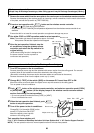
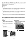
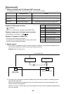
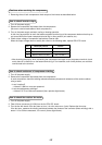
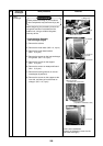
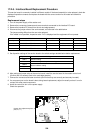
In case of increase the address-undefined indoor units (Extension, etc.)
If set up the indoor address of which address is undefined accompanied with extension of indoor units, replace-
ment of P.C. board, etc, follow to the methods below.
Method 1
Set up an address individually from a wired remote controller.
(Line address, Indoor address, Group address, Central address)
For the setup method, refer to the above “Manual address setup from remote controller”.
Method 2
Set up an address from the outdoor unit.
∗ Leave the address of the unit of which address has been already set up as it is.
Set up an address only to the unit of which address is undefined.
The addresses are allocated from the low number.
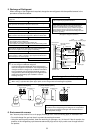
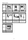
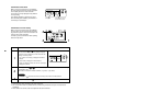
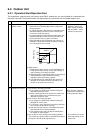
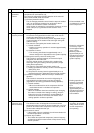
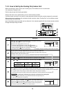
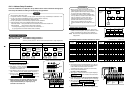
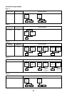
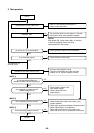
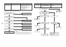
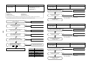
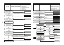
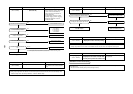
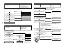
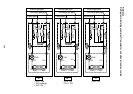
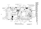
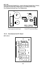
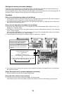
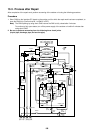
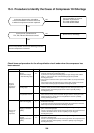
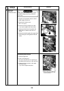
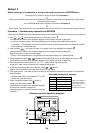
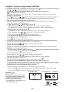
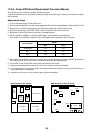
Setup procedure
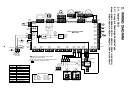
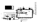
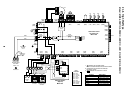
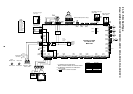
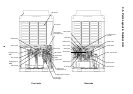
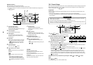
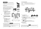
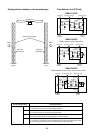
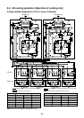
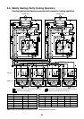
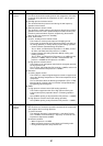
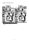
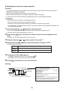
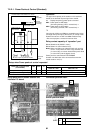
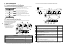
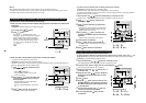
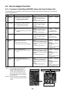
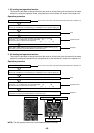
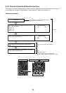
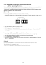
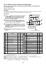
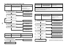
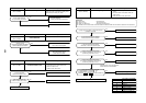
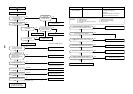
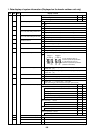
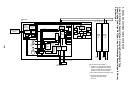
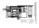
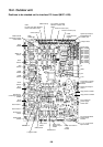
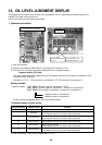
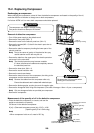
Arrange the outdoor header units in the refrigerant line to which indoor units are added. (Figure below)
1. Remove the relay connector between [U1U2] and [U3U4].
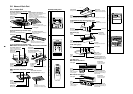
2. Turn on SW30-2 on the interface P.C. board at outdoor header unit side if it is OFF.
∗ Turn off the power, and then execute the operation.
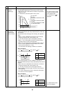
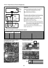
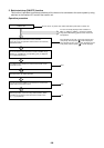
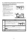
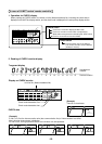
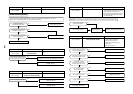
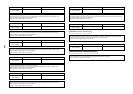
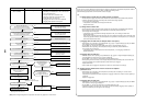
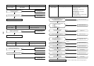
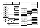
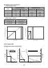
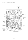
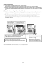
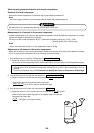
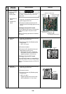
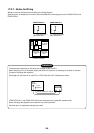
“AUTO1” → “AUTO2” → “AUTO3” →
…
→ “AUTO9” … is counted and displayed on 7-degment display.
• Return the SW01, 02, 03 setup as before.
5. When “U.1. - - -” is displayed on 7-segment display, the setup operation finished.
Turn off the indoor/outdoor power.
6. Return the following setup as before.
• Relay connector
• SW30-2
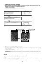
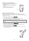
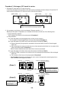
3. Turn on the indoor/outdoor power of which address is to be set up. After approx. 1 minute, check that
“U.1. - - -” is displayed on 7-segment display.
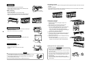
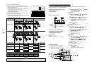
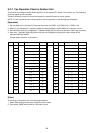
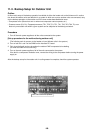
4. Execute the following operation on the interface P.C. board of the header unit.
SW01 SW02 SW03
2142
SW04
After checking that “ ” is displayed on 7-segment
display, and then push SW04 for 5 seconds or more.
U3 U4
U1 U2 U5 U6
U1 U2
A B
Header unit
Remote
controller
U3 U4
U1 U2 U5 U6
U1 U2
A B
Follower unit
Remote
controller
U3 U4
U1 U2 U5 U6
U1 U2
A B
Remote
controller
U3 U4
U1 U2 U5 U6
U1 U2
A B
Follower unit
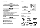
U3 U4
U1 U2
U1
U3
U2
U4
U5 U6
U1 U2
A B
Remote
controller
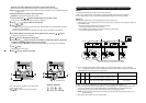
Center unit Center unitHeader unit Header unit
Central control
device
Added indoor unit
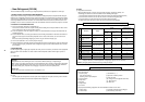
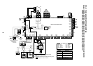
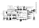
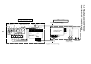
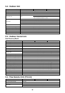
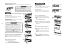
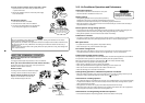
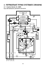
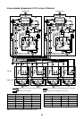
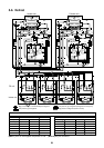
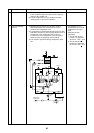
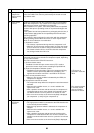
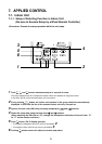
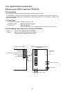
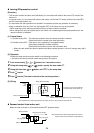
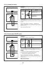
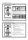
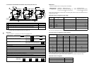
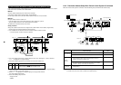
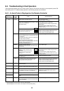
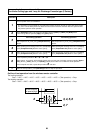
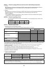
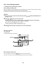
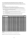
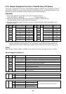
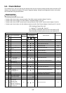
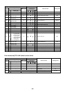
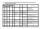
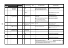
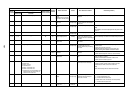
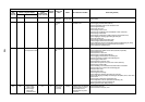
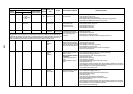
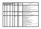
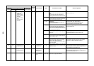
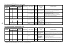
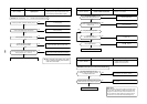
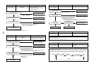
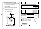
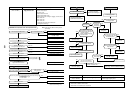
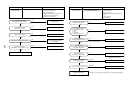
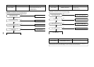
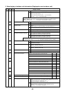
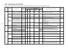
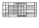
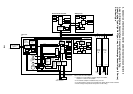
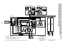
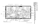
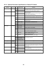
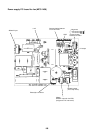
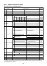
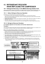
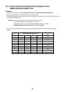
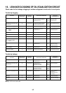
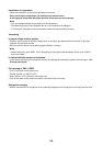
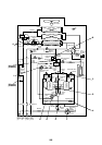
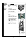
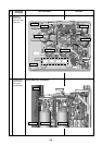
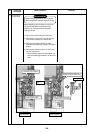
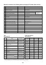
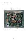
8-4-4. Check after Address Setup When Central Control System is Connected
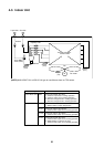
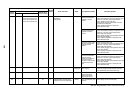
When the central control system is connected, check the following setup has finished after address setup.
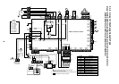
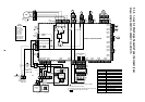
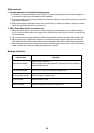
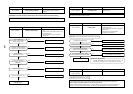
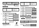
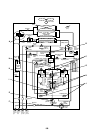
Note) The above table does not describe all the electric cablings. For details, refer to each installation manual
for outdoor unit, indoor unit, remote controller, and optional devices.
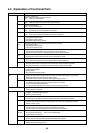
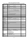
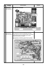
Relay connector
Terminal
resistance
Line address
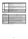
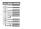
Main check items
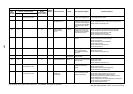
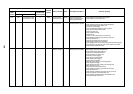
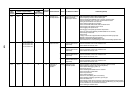
1) Is relay connector of the header unit connected after address setup?
2) Is relay connector of the follower unit removed?
3) Is the end resistance (SW30-2) of the header unit with the least refriger-
ant line address number (in the central control line) turned on?
(Setup is unnecessary for follower unit.)
4) Are the terminal resistance (SW30-2) of the header units except for the
line of which central control refrigerant line address is the smallest,
turned off? (Setup is unnecessary for follower unit.)
5) Are not addresses in the line address (SW13, SW14) duplicated in each
refrigerant line?
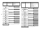
Check
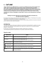
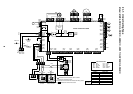
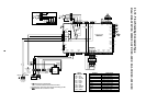
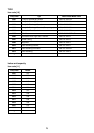
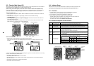
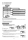
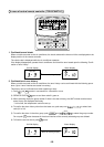
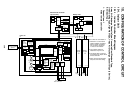
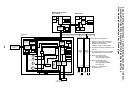
U1
U3
U2
U4
U1
U3
U2 U5 U6
U4
U1
U3
U2
U1
A
U2
U5 U6
U4
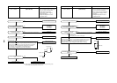
Header unit (A)
U1
U3
U2 U5 U6
U4
Follower unit (B)
U1
U3
U2 U5 U6
U4
Follower unit (C)
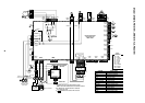
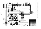
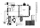
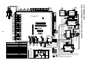
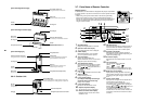
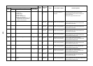
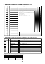
Outdoor unit
Indoor unit
Central control units
Line address = 2
Other refrigerant line
Other refrigerant line
Earth
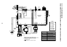
3-phase 380–415V, 50Hz
Leak interception
Main switch
1-phase 220–240V, 50Hz
Leak interception
Main switch
B
Remote
controller
U1
A
U2
B
Remote
controller
U1
A
U2
B
Remote
controller
U1
A
U2
B
5
3
2
5
Center unit (A)Center unit (A)
Header unit (A)
Line address = 1
1
4