


37
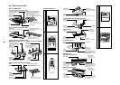
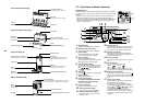
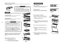
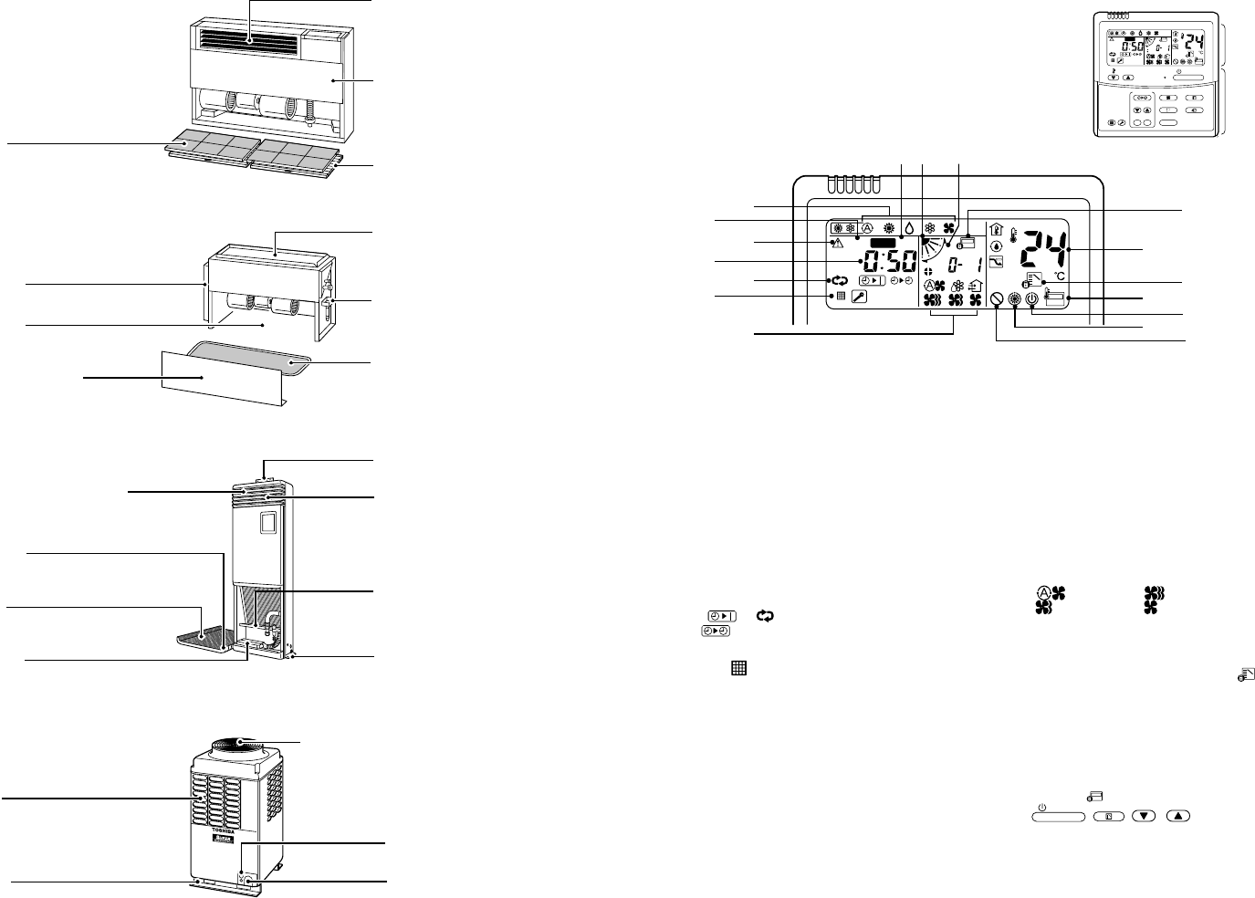
Air outlet/Air outlet louver
Changes the direction of the air flow.
Earth screw
Situated inside the electric parts box.
Air inlet grille
Air filter
Filters dust and other trash.
(Situated inside the air grille.)
Air outlet port
Drain pan (With drain filter)
This accessory is installed at the local site.
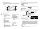
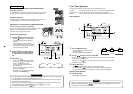
Air filter
Filters dust and other trash.
(Situated inside the suction port.)
Air inlet grille
Earth screw
Situated inside the electric parts box.
Earth screw
Situated inside the electric parts box.
Front panel (Lower side)
Vertical louver
The air can automatically be discharged
rightward/leftward at stated periods.
Fixing metal holder
Horizontal louver/Air outlet port
Changes the direction of the air flow.
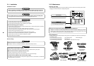
Air filter
Filters dust and other trash.
Air inlet grille
Fixing metal holder (Right and left)
Drain pan
Water accumulated in the drain pan is
drained through the drain pipe.
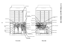
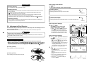
Air inlet
Situated at front, rear, left,
and right sides.
Fixing leg
Air outlet (Discharge)
Hot air is discharged when cooling operation is performed.
Cold air is discharged when heating operation is performed.
Power source aperture
Refrigerant pipe access for connection
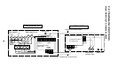
[Floor Standing Cabinet Type]
[Floor Standing Concealed Type]
[Floor Standing Type]
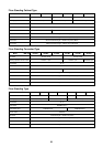
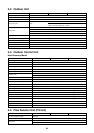
3-6-2. Outdoor Unit
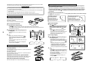
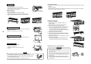
1
SET DATA display
Displayed during initialization of controller.
2
Operation mode select display
The selected operation mode is displayed.
3
CHECK display
Will be displayed when a error condition
occurs or a protection device operates.
4
Timer time display
Displays the selected delay time.
(When a malfunction occurs, a check code is
displayed in place of the time display.)
5
Timer SETIN setup display
By pressing the Timer Set button, the display
of the timer is shown in the following order:
[OFF]
→ [OFF] repeat OFF timer →
[ON]
→ No display.
6
Filter display
If “FILTER ” is displayed, clean the air filter.
7
TEST run display
Displayed during a test run.
8
Louver position display
(for 4-Way Air Discharge Cassette Type
and Under Ceiling Type model only)
Displays louver position.
9
Louver swing display
Indicates the movement of the louver.
10
Setpoint temperature display
The selected set up temp. is displayed.
11
Remote controller sensor display
Displayed while the sensor of the remote
controller is used.
12
PRE-HEAT display
Displayed when the heating or defrost operation is
carried out. While this indication is displayed, the
indoor fan stops or the runs in LOW fan speed.
13
Operation ready display
Displayed when cooling or heating operation is
impossible because the outdoor temperature goes
outside the operating range.
14
No function display
Displayed when the selected function is not avail-
able.
15
Fan mode display
The selected Fan mode is displayed.
(AUTO)
(HIGH)
(MED.) (LOW)
In the Concealed Duct High Static Pressure type
models, [HIGH] only is displayed for the air speed.
16
Mode select control display
Displayed when pushing “Operation mode select ”
button while the operation mode is fixed to heating
or cooling by the system manager of the air condi-
tioner.
17
Central control display
Displayed when using the remote controller with a
central control remote controller, etc.
If the remote controller is prohibited on fan the
centralcontrol side,
flashes when operating the
following
ON / OFF
,
MODE
, / buttons and
the function is not accepted.
(The different settings available on the remote
controller when in use with a central controller, can
be referred to in the owners manual of the central
controller.)
Display
section
Operation
section
ON / OFF
FAN
TEMP.
SWING/FIXTIME
MODE
VENT
UNITSET CL
FILTER
RESET
TEST
TIMER SET
CODE No.
UNIT No.
TEST
SETTING
DATA
SET
R.C. No.
H
2
15
5
78 9
3
1
4
6
10
11
13
16
12
14
17
CODE No.
UNIT No.
TEST
SETTING
DATA
SET
R.C. No.
H
3-7. Parts Name of Remote Controller
Display section
In the illustration, all of the indicators are displayed for the purpose of explanation.
In normal operation, only the icons relevant to the mode of operation would be
displayed.
• When turning on the power breaker switch for the first time, [SET DATA]
flashes on the display part of the remote controller. While this display is
flashing, the system is performing a self-check function. Wait until this check
has been completed and the [SET DATA] display has disappeared before
using the remote controller.