


133
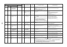
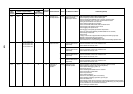
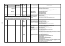
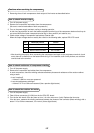
Check code
Outdoor 7-segment display
Main
remote
controller
Check code Sub-code
AI-NET
central control
remote controller
Detected
position
Check code
name
Status Error detection condition Check item (position)
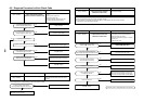
P07 P07 01: Compressor
1 side
02: Compressor
2 side
1C IPDU
I/F
Heat sink
overheat error
All stop IGBT built-in temp sensor (TH)
was overheated.
• Check power voltage.
• Check outdoor fan system error.
• Check clogging of heat sink cooling duct.
• Check fixation between IGBT and heat sink. (Check screwing and contact.)
• Check IPDU error.(IGBT built-in temp sensor (TH) error).
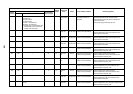
P10 P10
Indoor address
with trouble
Ob Indoor
Indoor
overflow error
All stop
• Float switch operated.
• Float switch circuit
disconnected or the
connector came off.
• Check the float switch connector.
• Check operation of drain pump unit.
• Check the drain pump circuit.
• Check clogging of drain pipe.
• Check indoor P.C. board error.
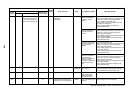
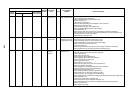
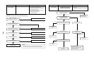
P12 —— 11 Indoor
Indoor fan
motor error
Correspondin
g
unit only stops.
The standard ducted unit air conditioner utilizes a direct current (DC) indoor fan motor that features current
limiting protection. In the event power is not isolated prior to service, the protective control circuit will activate
and stop the unit operating. The check code “P12”will be displayed on the remote controller-once service work
has been completed, this code can be cleared by switching off then on the electrical isolation device of the
indoor unit and pressing the operation stop button on the remote controller to reset the system
• The value of motor speed
deviated from target value
was detected for certain time.
• Over-current protection
operated.
• Check connection of fan connector and wiring.
• Check fan motor error.
• Check indoor P.C. board error.
• Check influence of outside air control.
• Check indoor type code (DN=10) and the capacity code (DN=11).
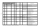
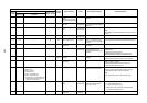
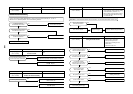
P13 P13 — 47 I/F
Outdoor li
q
uid
back
detection
error
All stop
In heating
While the system is operating
in HEAT mode, outdoor PMV of
which openin
g
de
g
ree was 100
pulse or less for a certain time.
• Check full close operation of outdoor PMV (1, 2).
• Check Pd and Ps sensor error.
• Check clogging of SV2 circuit.
• Check clogging of 4-way valve error circuit.
• Check outdoor P.C. board (I/F) error.
• Check capillary clogging of oil return circuit from oil separator.
• Check TS1, TS2 sensor error.
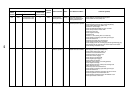
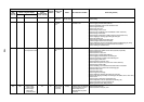
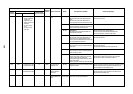
01: TS condition AE I/F Gas leak
detection
(TS1
condition)
All stop Suction temp exceeded the
judgment standard temp for 10
minutes or more.
TS error judgment standard
temperature
In cooling operation: 60°C or
higher
In heating operation: 40°C or
higher
• Check refrigerant shortage.
• Check full open of outdoor service valves (gas side, liquid side).
• Check outdoor PMV clogging (PMV1, 2).
• Check characteristics of TS1 sensor resistance value.
• Check 4-way valve error.
• Check leakage of SV4 circuit.
• Check leakage of SV5 circuit.
• Check mispiping of discharge gas/suction gas main pipe.
• Check Flow selector unit.
Check leakage of SVD valve and SVS valve. (Check leakage of SVDD valve and SVSS.)
Check mispiping of FS unit connecting pipe (Suction gas/Discharge gas), wiring between
FS unit and indoor unit, and connection of connectors.
Check miswiring of SVS/SVD valves.
P15 P15
02: TD condition
AE I/F Gas leak
detection
(TD condition)
All stop Discharge temperature TD1 or
TD2 was continuously 108°C
or higher for 10 minutes.
• Check refrigerant shortage.
• Check outdoor PMV clogging (PMV1, 2).
• Check characteristics of TD1, TD2 sensor resistance value.
• Check indoor air filter clogging.
• Check pipe clogging.
• Check SV4 circuit (Valve leakage, misinstallation)
• Check mispiping of discharge gas/suction gas main pipe.
• Check Flow selector unit.
Check leakage of SVD valve and SVS valve. (Check leakage of SVDD valve and SVSS.)
Check mispiping of FS unit connecting pipe (Suction gas/Discharge gas), wiring between
FS unit and indoor unit, and connection of connectors.
Check miswiring of SVS/SVD valves.