


215
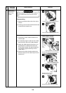
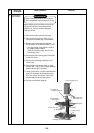
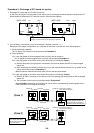
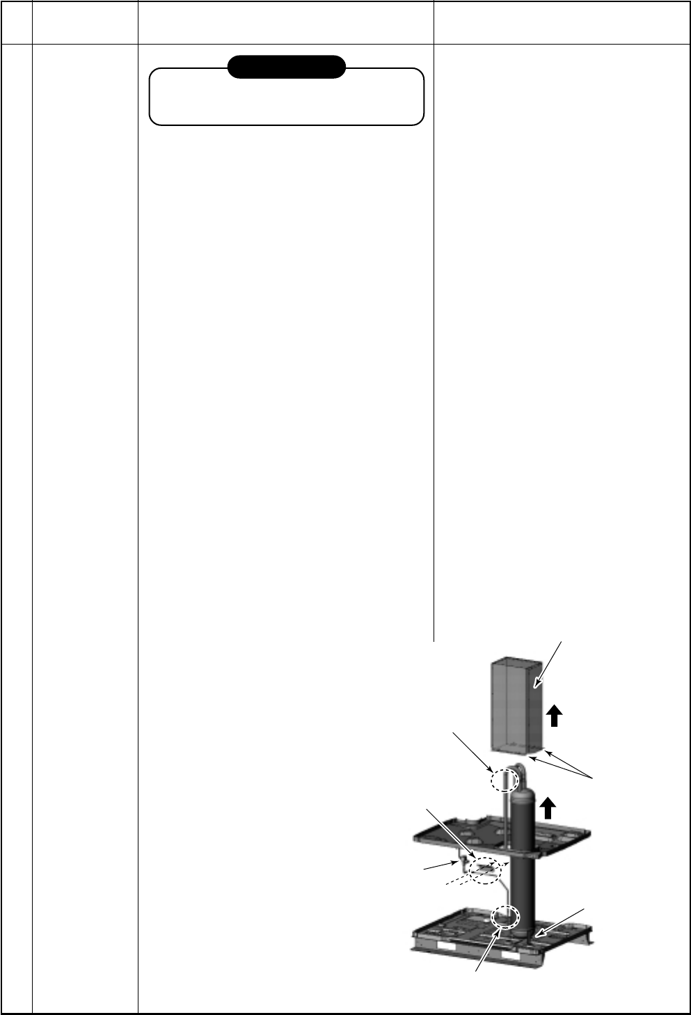
4) Brazing part with SV2 assembly
6) Accumulator cover
6) Two screws each
at front and rear
8)
6)
7) Cut pipe at
entrance/exit ports.
3) Accumulator
fixing board
Middle par
Middle par
tition board
tition board
Middle partition board
4) SV2 valve
3) Two screws
Accumulator
2) Three screws
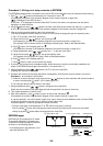
No.
9
Part to be
exchanged
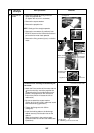
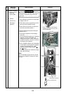
Exchange of
accumulator
Work procedure
REQUIREMENT
Wear protective clothing on your hands as
other components may cause and injury etc.
Before beginning the procedure, ensure the
refrigerant has been reclaimed from the
outdoor unit, using a suitable refrigerant
recovery device.
1) Remove the lower cabinet (rear side).
2) Remove the fixing screws (M6 × 3 pcs.)
from the accumulator leg ⇔ base board.
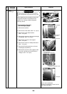
3) Remove the accumulator fixing board ∗ ⇔
fixing screws on accumulator (M6 × 2 pcs.)
∗ The accumulator fixing board is fixed to
the middle partition board.
(Take off only the screws, which fix the
accumulator unit.)
4) Remove the pipe (brazing part) connected
to the SV2 valve.
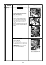
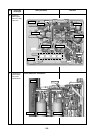
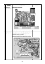
5) Remove the discharge cabinet fan and
motor base.
6) Remove the accumulator cover ⇔ fixing
screws (M5 × 4 pcs.) of the middle partition
board and then pull it upwards.
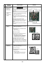
7) Using a pipe cutter, cut off the entrance/exit
pipe of accumulator at the specified posi-
tion. (For the cut-off position, refer to the
Manual attached to the repair parts.)
8) Pull the accumulator upwards.
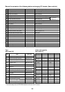
Remarks