


177
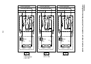
Remote
controller
communication
circuit
CPU
H8/3039
Driver
Remote
controller
communication
circuit
Power
circuit
Transformer
Transformer
Switch
setup
Same
as left
*2
#2
AB
L
U1 U2
N
L
AB
NU1 U2
U1 U2
Power
supply
Outdoor
unit
Same
as left
*2
#3
AB
L
U1 U2
N
Power
supply
Outdoor
unit
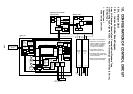
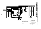
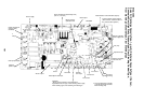
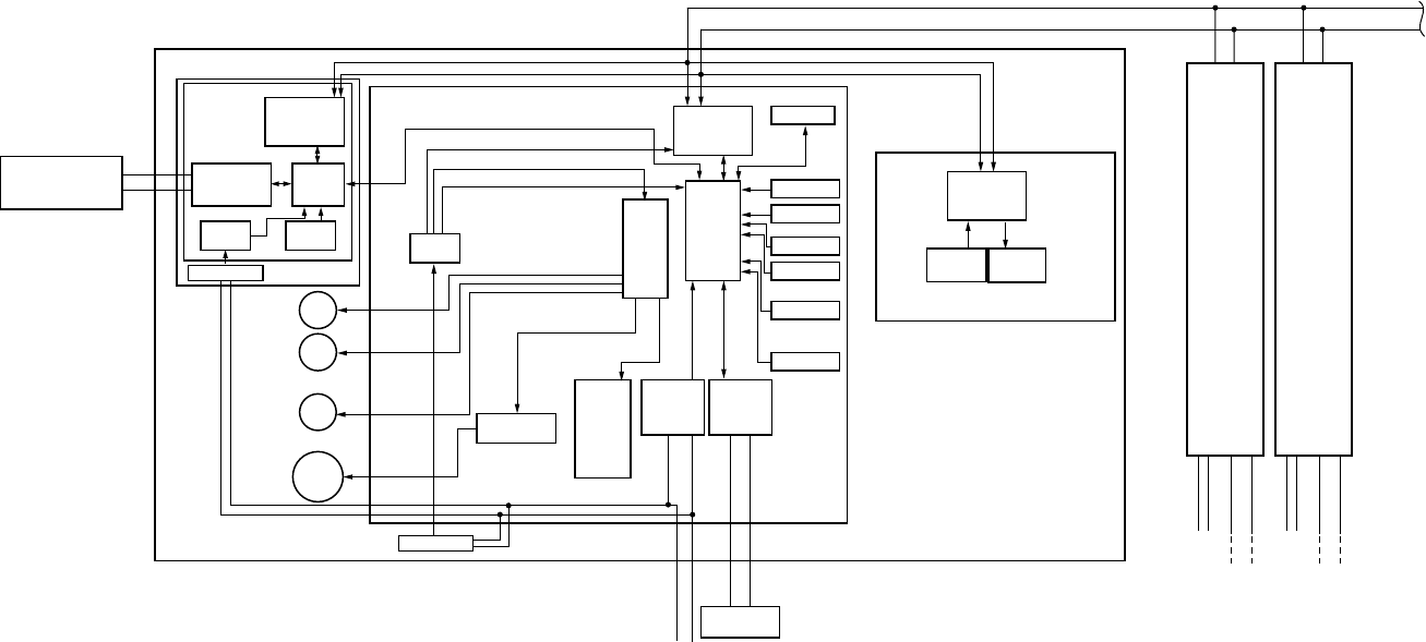
Network adaptor (Option)
Indoor unit
#1
Central control
remote controller
(Option)
X
Y
(In case of AI-NETWORK)
Network
adaptor
P.C. board
(MCC-1401)
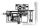
Indoor control P.C. board (MCC-1403)
DC5V
DC20V
DC12V
DC5V
AI-NET
communication
circuit
CPU
H8/3687
PMV
Louver
motor
Drain
pump
Indoor
fan motor
EEPROM
TA sensor
TCI sensor
TC2 sensor
TCJ sensor
Float input
HA
BUS
communication
circuit
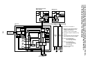
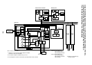
Outdoor unit
Power supply
1Ø220-240V, 50Hz
AC
synchronous
signal input
circuit
Fan motor
control circuit
Start
Alarm
Ready
Thermostat ON
COOL
HEAT
FAN
Indoor/Outdoor
communication
Outside
output
Power
circuit
Remote
controller
communication
circuit
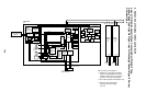
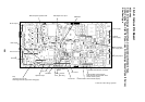
*3 Nome for concealed duct,
Floor standing cabinet
Floor standing concealed
*4 Nome for concealed duct,
Floor standing cabinet
Floor standing concealed
Floor standing
*5 Nome for 1-way discharge
cassette YH type.
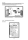
Max. 8 units are connectable. *1
*1 However in a case that the network
adaptor is installed when 2 wireless
remote controller kits are connected,
maximum 7 units are connectable.
*2 The network adaptor is installed to only
one unit.
Sensors
Wireless remote
controller kit
Display
section
None for
Concealed Duct
*3
*4
*5
*4
2-way Air Discharge Cassette Type, 1-way Air Discharge Cassette Type (1 Series),
Concealed Duct High Static Pressure Type, Floor Standing Cabinet Type,
Floor Standing Concealed Type, Floor Standing Type