


Advanced Topics in SPA9000 Administration
SPA9000 Architecture
SPA9000 Voice System Administration Guide 170
A
SPA9000 Architecture
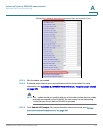
This section describes the basic architecture, function, and configuration options
for the SPA9000.
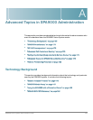
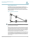
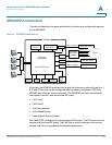
Figure 4 SPA9000 Architecture
As shown, the SPA9000 provides four logical line interfaces, referred to as Line 1,
2, 3, and 4. Each line can be configured with the same or a different ITSP. Each
SPA400 also occupies one line interface. The SPA9000 has five internal clients
that register implicitly with the internal SIP proxy:
• FXS1 (fxs1)
• FXS2 (fxs2)
• Call Park (callpark)
• Auto-Attendant (aa)
• Internal Music Server (imusic)
FXS1 and FXS2 correspond to the two physical FXS ports. The FXS ports can only
register with the local SIP proxy. The Call Park is used to maintain calls that are
parked, and AA is a scriptable auto-attendant application.
imusic
Line 1
ITSP SIP Proxy
(408)111-1000 to 7
(949)111-2000 to 7
(888)111-3000 to 7
ITSP SIP Proxy
ITSP SIP Proxy
SPA9000
aa
PSTN
SPA 400
SIP-PSTN
gateway
(408)111-1111
(408)111-1112
(408)111-1113
(408)111-1114
Line 2
Line 3
Line 4
FXS1
Application
server
Switch
FXS2
SIP Proxy
SIP Registrar
Media (RTP) Proxy
Call
park
Administration
web server