


*
INTEGRATED OUTPUT SECTION
9.21
*
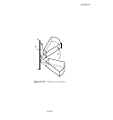
INTEGRATED OUTPUT SECTION: Define an integrated output section over a surface
with a local coordinate system and a reference point.
This option is used to associate a surface with a coordinate system and/or a reference node to track the average
motion of the surface. It can also be used in conjunction with an integrated output request to obtain output of
quantities integrated over a surface.
Product: ABAQUS/Explicit
Type: Model data
Level: Part, Part instance, Assembly
References:
•
“Integrated output section definition,” Sec tion 2.5.1 of the ABAQUS Analysis User’s Manual
•
“Output to the output database,” Section 4.1.3 of the ABAQUS Analysis User’s Manual
• *
INTEGRATED OUTPUT
• *
SURFACE
Required parameters:
NAME
Set this parameter equal to a label that will be used to refer to the integrated output section.
SURFACE
Set this parameter equal to the name of the surface (see “Defining elem ent-based surfaces,”
Section 2.3.2 of the ABAQUS Analysis User’s Manual) to be associated w ith the integrated output
section.
Optional parameters:
ORIENTATION
Set this parameter equal to the name of an orientation definition (“Orientations,” Section 2.2.5 of
the ABAQUS Analysis User’s Manual) to define the initial coordinate system for the section. This
initial system can be further modified by using the PROJECT ORIENTATION param eter.
If this parameter is omitted, the global c oordinate system is used.
POSITION
This parameter is relevant only if the REF NODE parameter is included.
Set POSITION=INPUT (default) if the location of the reference node is to be defined by the
user.
9.21–1
ABAQUS Version 6.1 Module:
ID:
Printed on: