


*
NCOPY
2. Y-coordinate of the first point definin g the reflection pla ne.
3. Z-coordinate of the first point defining the reflec tion plane.
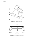
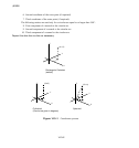
4. X-coordinate of the second point defining the reflection plane (point b in Figure 14.1–3).
5. Y-coordinate of the second point defining the reflection plane.
6. Z-coordinate of the second point defining the refle ction plane.
Second line:
1. X-coordinate of the third point defining the reflection plane (point c in Figure 14.1–3).
2. Y-coordinate of the third point defining the reflection plane.
3. Z-coordinate of the third point defining the reflection plane.
Data line if REFLECT=POINT:
First (and only) line:
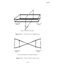
1. X-coordinate of the reflection point (point a in Figure 14.1–4).
2. Y-coordinate of the reflection point.
3. Z-coordinate of the reflec tion point.
Data line if the POLE parameter is included:
First (and only) line:
1. Number of th e pole node (optiona l: it must have been defined already).
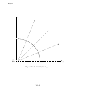
2. X-coordinate of the pole node (poi nt a in Figure 14.1–5, only required if the pole node number
was not entered).
3. Y-coordinate of the pole node (only required if the p ole node number was not entered).
4. Z-coordinate of the pole node (only required if the p ole nod e number was not entered).
14.1–3
ABAQUS Version 6.1 Module:
ID:
Printed on: