*
SIMPEDANCE
Optional parameter:
OP
Set OP=MOD (de fault) to m odify existing impedances or to define additional im pedances.
Set OP=NEW if all existing impedances applied to the model should be rem oved. To remove
only selected impedances, use OP=NEW and respecify all impedances that are to be retained.
Data line to define an impedance for PROPERTY, N ONR EFLECTING=PLANAR, or
NONREFLECTING=IMPROVED:
First (and only) line:
1. Surface name.
Data line to define an absorbing boundary impedance for NONR EFLECTING=CIRCULAR or
NONREFLECTING=SPHERICAL:
First (and only) line:
1. Surface name.
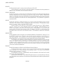
2.
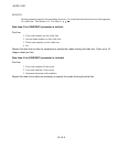
, the radius of the circle or sphere defining the absorbing boundary surface.
Data line to define an absorbing boundary impedance for NONREFLECTING=ELLIPTICAL or
NONREFLECTING=PROLATE SPHEROIDAL:
First (and only) line:
1. Surface name.
2. The semimajor axis, a, of the ellipse or prolate spheroid defining the surface. a is 1/2 of the
maximum distance between two points on the ellipse or spheroid, analogous to the radius of a
circle or sphere.
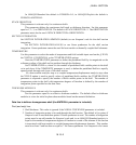
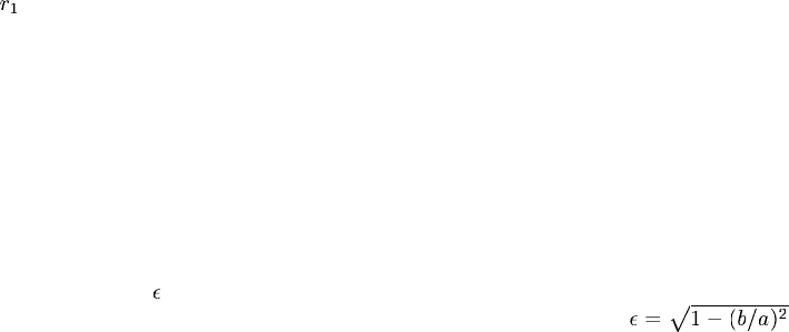
3. The eccentricity,
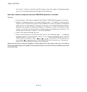
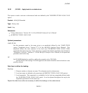
, of the ellipse or prolate spheroid. The eccentricity is the square root of one
minus the square of the ratio of the minor axis, b, to the major axis, a:
.
4. Global X-coordinate of the center of the radiating surface.
5. Global Y-coordinate of the center of the radiating surface.
6. Global Z-coordinate of the center of the radiating surface.
7. X-component of the direction cosine ofthe major axisof the radiatingsurface. Thecomponents
of this vector need not be normaliz ed to unit magnitude.
8. Y-com ponent of the direction cosine of the major axis of the radiating surface.
9. Z-com ponent of the direction cosine of the major axis of the radiating surface.
18.17–2
ABAQUS Version 6.1 Module:
ID:
Printed on:


