


*
NCOPY
Optional parameters:
MULTIPLE
This parameter is used with the SHIFT parameter to define the number of times the rotation should
be applied. The default is MULTIPLE=1.
NEW SET
Set this parameter equal to the name of the node set to which the nodes created by the operation
will be assigned. This new node set will be unsorted if the OLD SET was unsorted and if the N EW
SET does not already exist. Otherwise, this new node set will be a sorted set.
If this parameter is omitted, the newly created nodes are not assigned to a node set.
Data lines if the SHIFT parameter is included:
First line:
1. Value of the translation to be appli ed in the X-direc tion.
2. Value of the translation to be appli ed in the Y-direc tion.
3. Value of the transla tion to be applied in the Z-direction.
Second line:
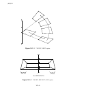
1. X-coordinate of the first point defining the rotation axis (point a in Figure 14.1–1).
2. Y-coordinate of the first point defining the rotation axis.
3. Z-coordinate of the first point defining the ro tation axis.
4. X-coordinate of the second point defining the rotation axis (point b in Figure 14.1–1).
5. Y-coordinate of the sec ond point defining the rotation a xis.
6. Z-coordinate of the second point defining the rotation axis.
7. Angle of rotation about the axis a–b, in degrees.
Data line if REFLECT=LINE :
First (and only) line:
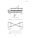
1. X-coordinate of the first point defining the reflection line (point a in Figure 14.1–2).
2. Y-coordinate of the first point defining the reflection line.
3. Z-coordinate of the first point defining the reflection line.
4. X-coordinate of the second point defining the reflection line (point b in Figure 14.1–2).
5. Y-coordinate of the second point defining the reflection line.
6. Z-coordinate of the second point defining the reflection line.
Data lines if REFLECT=MIRROR:
First line:
1. X-coordinate of the first point defining the reflection plane (point a in Figure 14.1–3).
14.1–2
ABAQUS Version 6.1 Module:
ID:
Printed on: