


*
PARAMETER SHAPE VARIATION
Optional parameters if the FILE parameter is used:
INC
Set this parameter equal to the increment number (in the analysis whose results file is being used as
input to this option) from which the displacement data are to be read. If this parameter is omitted,
ABAQUS will read the data from the last increment available for the specified step on the results
file.
MODE
Set this parameter equal to the mode num ber (in the analysis whose results file is being used as input
to this option) from which the modal data are to be read. If this parameter is omitted, ABAQUS
will read the data from the first mode available for the specified step on the results file.
NSET
Set this para meter equal to the node set to which the s hape variation values are to be applied. If this
parameter is omitted, the shape variation will be applied to all nodes in the model.
Optional parameter if the FILE parameter is omitted:
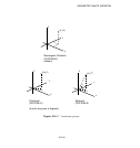
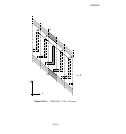
SYSTEM
Set SYSTEM=R (default) to specify the shape variation as values of Cartesian coordinates. Set
SYSTEM=C to specify the shape variation as values of cylindrical coordinates. Set SYSTEM=S to
specify the shape variation as values of spherical coordinates. See Figure 16.3–1.
The SYSTEM parameter is entirely local to this option and should not be confused with the
*
SYSTEM option. As the data lines are read, the shape variation values specified are transformed
to the global rectangular Cartesian coordinate system. This transformation requires that the object
be centered about the origin of the global coordinate system; i.e., the
*
SYSTEM option should
be off w hen specify ing shape variations as values using eithe r cylindrical or sphe rical coordinates.
The details of how the shape variation is computed in particular coordinate systems are given in
“Parametric shape variation,” Section 2.1.2 of the ABA QUS Analysis User’s Manual.
Data lines to define the shape variation if the FILE and INPUT parameters are omitted:
First line:
1. Node number or node set.
2. Component of shape variation in the first coordinate direction.
3. Component of shape variation in the second coordinate direction.
4. Component of shape variation in the third coordinate direction.
5. Shape variation in the first normal component.
6. Shape variation in the second normal component.
7. Shape variation in the third norma l component.
Repeat this data line as often as necessary to define the shape variation. The data g iven on this data
line cannot be parameterized.
16.3–2
ABAQUS Version 6.1 Module:
ID:
Printed on: