*
ORIENTATION
SYSTEM
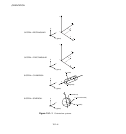
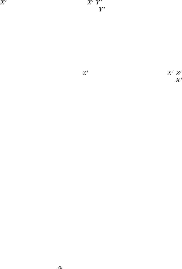
Set SYSTEM=RECTANGULAR (default) to define a rectangular Cartesian system by the three
points a, b,andc shown in Figure 15.1–1. Point c is the origin of the system, point a must lie on the
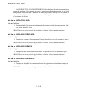
-axis, and point b must lie on the - plane. A lthough not necessary, it is intuitive to select
point b such that it is on or near the local
-axis.
Set SYSTEM=CYLINDRICAL to define a cylindrical system by giving the two points
a and b on the polar axis of the cylindrical system (Figure 15.1–1). The local axes are 1=radial,
2=circumferential, 3=axial.
Set SYSTEM=SPHERICAL to define a spherical system by giving the center of the sphere,
a, and point b on the polar axis (Figure 15.1–1). The local axes are 1=radial, 2=circumferential,
3=meridional.
Set SYSTEM=Z RECTANGULAR in an ABAQUS/Standard analysis to define a rectangular
Cartesian system by the thre e points a, b,andc shown in Figure 15.1–1. Point c is the origin of
the system, point a must lie on the
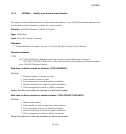
-axis, and point b must lie on the - plane . Although not
necessary, it is intuitive to select point b such that it is on or near the local
-axis.
Set SYSTEM=USER in an ABAQUS/Standard analysis to define the local coordinate system
in user subroutine ORIENT. The DEFINITION parameter, and any data lines associated w ith the
option are ignored if SYSTEM=USER.
Data lines to define an orientation using DEFINITION=COORDINATES:
First line:
1. X-coordinate of point a.
2. Y-coordinate of point a.
3. Z-coordinate of point a.
4. X-coordinate of point b.
5. Y-coordinate of point b.
6. Z-coordinate of point b.
The following items, the coordinates of point c (the origin), are optional and relevant only for
SYSTEM=RECTANGULAR and SYSTEM=Z RECTANGULAR. The default location of the
origin, c, is the global origin.
7. X-coordinate of point c.
8. Y-coordinate of point c.
9. Z-coordinate of point c.
Second line (mandatory for shells, membranes, gaskets, composite solid sections, and contact pairs):
1. Local direction about which the additional rotation or rotations are given. The default is the
local 1-direction. For shell, membrane, and cohesive elements this direction should have a
nonzero component in the direction of the normal to the surface.
2. Additional rotation
(in degrees) applied to both directions orthogonal to the specified local
direction. The default is zero degrees.
15.1–2
ABAQUS Version 6.1 Module:
ID:
Printed on:


