


*
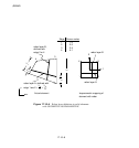
REBAR
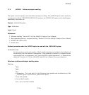
3
2
1
4
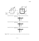
Similar to
edge 1 or 3
S
imilar to
e
dge 2 or 4
1 1-2
2 2-3
3 3-4
4 4-1
Edge Corner node
s
4
2
2
3
1
1
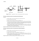
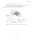
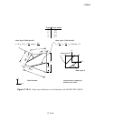
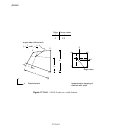
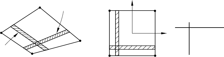
physical space
isoparametric space
Figure 17.10–2 “Isoparametric” rebar in a three-dimensional shell or membrane.
Data lines to define skew rebar in three-dimensional shell elements:
First line:
1. Element num ber or name of the element set that contains these rebar.
2. Cross-sectional area of each rebar.
3. Spacing of rebar in the plane of the shell. The default is 1.0.
4. Position of the rebar in the shell section thickness direction. This value is given as the distance
of the reb ar from the middle surface of the shell, positive in the direction of the positive normal
to the shell. This value is modified if the NODAL THICKNESS parameter is included w ith
the
*
SHELL SECTION option of the underlying shell element.
5. Angular orientation of rebar (in degrees) between the positive local 1-direction and the rebar.
The optional ORIENTATION parameter given on the
*
SHELL SECTION option should hav e
no influence on the rebar angular orientation.
Repeat this data line as often as necessar y. Each line defines a layer of rebar.
Data lines to define skew rebar in three-dimensional membrane elements:
First line:
1. Element num ber or name of the element set that contains these rebar.
2. Cross-sectional area of each rebar.
3. Spacing of rebar in the plane of the membrane . The default is 1.0.
4. Angular orientation of rebar (in degrees) between the positive local 1-direction and the rebar.
The optional ORIENTATION parameter given on the
*
MEMBRANE SECTION option should
have no influence on the rebar angular orientation.
Repeat this data line as often as necessar y. Each line defines a layer of rebar.
17.10–4
ABAQUS Version 6.1 Module:
ID:
Printed on: