*
SECTION POINTS
4. Local -position of second sec tion point.
Continue giving coordinate pairs for as many points as needed. At most four pairs of points can
be specified on any data line. If the point (0,0) is specified as the last entry on a line, it will be ignored
unless it is the o nly point requested.
Data lines to locate elements and integration point numbers for meshed sections when used in
conjunction with the
*
BEAM GENERAL SECTION, SECTION=MESHED option:
First line:
1. Section point label.
2. Two-dimensional model element number.
3. Integration point num ber.
Second line:
1. Young’s modulus, E.
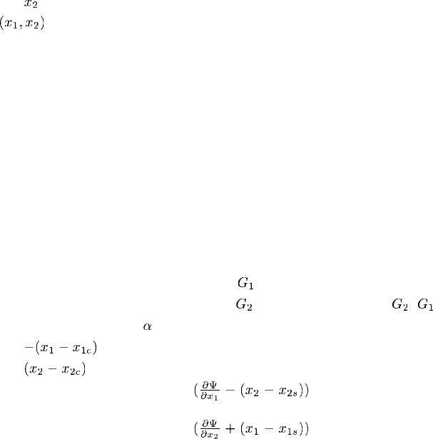
2. Shear modulus in user-defined 1-direction,
.
3. Shear modulus in use r-defined 2-direction,
(for isotropic materials = ).
4. Material orientation angle,
, measured counterclockwise from the beam local 1-direction.
5. Local
-position of the integration point with respect to the centroid.
6. Local
-position of the integration point with respect to the centroid.
7. Derivative of the warping function
with respect to the local 1-direction
and the shear center.
8. Derivative of the warping function
with respect to the local 2-direction
and the shear center.
Repeat this set of data lines for as many integration points as needed.
Data lines to locate elements and integration point numbers in the cross-section model when
used in conjunction with the
*
BEAM SECTION GEN ERATE option:
First line:
1. Section point label.
2. Element number.
3. Integration point num ber.
Repeat this data line as often as necessary to specify the elements and integration points.
18.4–2
ABAQUS Version 6.1 Module:
ID:
Printed on:


