*
SHELL GENERAL SECTION
Optional parameter for use when the MATERIAL, the COMPOSITE, and the USER parameters
are omitted:
DEPENDENCIES
Set this parameter equal to the number of field variable dependencies included in the definition of
the scaling moduli, in addition to temperature. If this param eter is omitted, it is assumed that the
moduli are constant or depend only on temperature.
Data line if the MATERIAL parameter is included:
First (and only) line:
1. Shell thickness. This value is ignored if the NODAL THICKNESS pa rameter is included.
Data lines if the COMPOSITE parameter is included:
First line:
1. Layer thickness. This value is scaled if the NOD AL THICKNESS parameter is included.
2. This field is not used (any value given will be ignored). It is included for compatibility with
the
*
SHELL SECTION option.
3. Name of the material forming this layer.
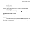
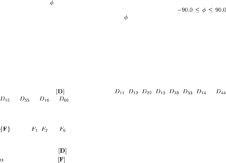
4. Orientation angle,
, (in degrees) measured positive counterclockwise relative to the
orientation definition given with the ORIENTATION parameter, where
.
If the ORIENTATION param eter is not included,
is measured relative to the default shell
local directions (see “Conventions,” Section 1.2.2 of the ABAQUS Analysis User ’s Manual).
Repeat this data line as often as necessa ry to define the layers of the shell. The order of the laminated
shell layers with respect to the positive direction of the shell normal is defined by the order of the data
lines.
Data lines to define the shell section if the MATERIAL, the COMPOSITE, and the USER
parameters are omitted:
First line:
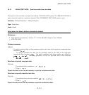
1. Symmetric half of the matrix in the order , , , , , , ,..., ,
,..., ,..., ,...,
Repeat this data line three times. Enter 21 entr ies total, 8 per line.
Second line (optional):
1. vector ( , , ..., ).
Third line (optional):
1. Y, scaling modulus for . The default is 1.0 .
2.
, scaling modulus for . The default is 0.0.
18.14–4
ABAQUS Version 6.1 Module:
ID:
Printed on:


