


*
TRANSFORM
19.10
*
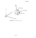
TRANSFORM: Specify a local coordinate system at nodes.
This option is used to specify a local coordinate system for displacement and rotation degrees of freedom at
a node.
Products: ABAQUS/Standard ABAQUS/Explicit
Type: Model data
Level: Part, Part instance, Assembly
Reference:
•
“Transformed coordinate systems,” Section 2.1.5 of the ABA QUS Analysis User’s Manual
Required parameter:
NSET
Set this parameter equal to the name of the node set for which the local transformed system is being
given.
Optional parameter:
TYPE
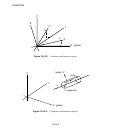
Set TYPE=R (default) to indicate a rectangular Cartesian system (Figure 19.10–1). Set TYPE=C
to indicate a cylindrical system (Figure 19.10–2). Set TYPE=S to indicate a spherical system
(Figure 19.10–3).
Data line to define a transformed coordinate system:
First (and only) line:
1. Global X-coordinate of point a specifying transformation.
2. Global Y-coordinate of point a specifying transformation.
3. Global Z-coordinate of point a specifying transform ation.
4. Global X-coordinate of point b specifying transformation.
5. Global Y-coordinate of point b specifying transformation.
6. Global Z-coordinate of point b specifying transformation.
19.10–1
ABAQUS Version 6.1 Module:
ID:
Printed on: