*
INITIAL CONDITIONS
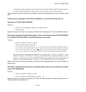
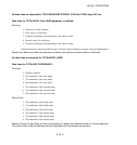
3. Vertical coordinate corresponding to the above value.
4. Second value of vertical component of (effective) stress.
5. Vertical coordinate corresponding to the above value.
6. First coefficient of lateral stress. This coefficient defines the x-direction stress components.
7. Second coefficient of lateral stress. This coefficient defines the y-direction stress component
in three-dimensional cases and th e thickness or hoop direction component in plane or
axisymmetric cases. If this value is omitted, it is assumed to be the same as the first lateral
stress coefficient given in the previous field.
Repeat this data line as often as necessary to define an initial geostatic stress state in var ious elements
or element sets.
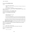
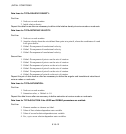
Data lines for TYPE=STRESS, REBAR:
First line:
1. Element number or element set label.
2. Rebar name. If this field is left blank, the stress is applied to all rebars in these elements.
3. Prestress value.
Repeat this data line as often as ne cessary to define initial stress in the rebars of various elements or
element sets.
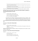
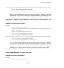
Data lines for TYPE=STRESS, SECTION POINTS:
First line:
1. Element number or element set label.
2. Section point number.
3. Value of first stress component.
4. Value of second stress component.
5. Etc., up to three stress components.
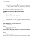
Give the stress com ponents as defined for this element type in Part VI, “Elements,” of the
ABAQUS Analysis User’s Manual. Stress values given on data lines are applied uniformly over
the element. In any element for which an
*
ORIENTATION option applies, the stresses must be
given in the local sy stem (“Orientations,” Section 2.2.5 of the A BAQ US Analysis User ’s M anual).
Repeat this data line as often as necessary to define initial stresses in various elements or element sets.
Stresses must be defined at all section points within an element.
9.18–15
ABAQUS Version 6.1 Module:
ID:
Printed on:


