


*
REBAR
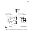
Data lines to define rebar in axisymmetric shell elements:
First line:
1. Element num ber or name of the element set that contains these rebar.
2. Cross-sectional area of each rebar.
3. Spacing of rebar in this rebar layer. The default is 1.0.
4. Position of the rebar in the shell section thickness direction. This value is given as the distance
of the reb ar from the middle surface of the shell, positive in the direction of the positive normal
to the shell. This value is modified if the NODAL THICKNESS parameter is included w ith
the
*
SHELL SECTION option of the underlying shell element.
5. Angular orientation of rebar from the meridional plane in degrees (0° is meridional, 90° is
circumferential). Positive rotation is about the positive normal to the shell.
6. Radial position at which the spacing of the rebar is measured. If this entry is nonzero, it is
assumed that the rebar spacing varies linearly with radial position. If this entry is zero or blank,
the rebar spacing does not vary with position. This entry has no meaning for circumferential
rebar.
Repeat this data line as often as necessar y. Each line defines a layer of rebar.
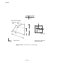
Data lines to define rebar in axisymmetric membrane elements:
First line:
1. Element num ber or name of the element set that contains these rebar.
2. Cross-sectional area of each rebar.
3. Spacing of rebar in this rebar layer. The default is 1.0.
4. Angular orientation of rebar from the meridional plane in degrees (0° is meridional, 90° is
circumferential). Positive rotation is about the positive normal to the membrane.
5. Radial position at which the spacing of the rebar is measured. If this entry is nonzero, it is
assumed that the rebar spacing varies linearly with radial position. If this entry is zero or blank,
the rebar spacing does not vary with position. This entry has no meaning for circumferential
rebar.
Repeat this data line as often as necessar y. Each line defines a layer of rebar.
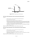
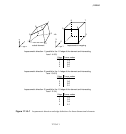
Data lines to define a layer of uniformly spaced rebar in continuum elements (SINGLE parameter
omitted) when the layer is parallel to two isoparametric directions in the element’s local
(isoparametric) coordinate system (GEOMETRY=ISOPARAMETRIC):
First line:
1. Element num ber or name of the element set that contains these rebar.
2. Cross-sectional area of each rebar.
3. Spacing of rebar. The default is 1.0.
17.10–5
ABAQUS Version 6.1 Module:
ID:
Printed on: