


*
NMAP
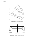
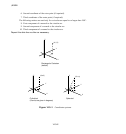
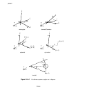
by the distance between points a and b. The line between points a and b defines the position.
For every value of
the -coordinate is defined in a plane perpendicular to the plane defined by
the points a, b,andc and perpendicular to the axis of the toroidal system.
lies in the plane
defined by the points by a, b,andc.
Set TYPE=BLENDED to map via blended quadratics in an ABAQUS/Standard analysis.
Data lines for TYPE=RECTANGULAR, CYLINDRICAL, DIAMOND, SPHERICAL, or TOROIDAL:
First line:
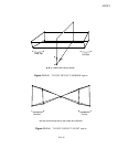
1. X-coordinate of point a (see Figur e 14.4–1).
2. Y-coordinate of point a.
3. Z-coordinate of point a.
4. X-coordinate of point b.
5. Y-coordinate of point b.
6. Z-coordinate of point b.
Second line:
1. X-coordinate of point c.
2. Y-coordinate of point c.
3. Z-coordinate of point c.
The following fields are needed only for TYPE=DIAMOND:
4. X-coordinate of point d.
5. Y-coordinate of point d.
6. Z-coordinate of point d.
If TYPE=RECTANGULAR is specified and only point a is given, the coordinates of the nodes in
the set are simply shifted by
, ,and .
Third line:
1. Scale factor to be applied to the first local coordinate before m apping. If the value entered is
zero or blank, a scale factor of 1.0 is assumed.
2. Scale factor to be applied to the second local coordinate before mapping. If the value entered
is zero or blank, a scale factor of 1.0 is assumed.
3. Scale factor to be applied to the third local coordinate before m apping. If the value entered is
zero or blank, a scale factor of 1.0 is assumed.
Data lines for TYPE=BLENDED:
First line:
1. Node number of the first control node.
2. X-coordinate of the point to which t his control node is to be mapped.
14.4–2
ABAQUS Version 6.1 Module:
ID:
Printed on: