


*
SURFACE
2. Face or edge identifier label (see “Defining element-based surfaces,” Section 2.3.2 of the
ABAQUS Analysis User’s Manual, for the face and edge identifiers for various elements) or
the “word” EDGE (optional).
Repeat this data line as often as necessar y to define the surface.
Data lines to define a surface using nodes or node sets when the TYPE=NODE parameter is used:
First line:
1. Node set name or node number.
2. Cross-sectional area or distributing weight factor. In ABAQUS/Standard contact calculations,
the default is the area specified in the associated
*
SURFACE INTERACTION option if the
surface is defined in a contact pair; otherwise, a unit area is used. In ABAQUS/Explicit the
cross-sectional area used for contact pair calculations for node-based surface nodes is always
set to 1.0 regardless of the value specified here. If the surface is used in a
*
COUPLING or
*
SHELL TO SOLID COUPLING d efinition, the default distributing weight factor is zero.
Repeat this data line as often as necessar y to define the surface.
Data lines to define a surface using a plane cutting through the given element sets when the
TYPE=CUTTING SURFACE parameter is used:
First line:
1. X-coordinate of a point on the cutting plane in the initial configuration.
2. Y-coordinate of a point on the cutting plane in the initial configuration.
3. Z-coordinate of a point on the cutting plane in the initial configura tion.
4. X-component of a normal to the cutting plane in the initial c onfiguration.
5. Y-component of a normal to the cutting plane in the initial configuration.
6. Z-component of a normal to the cutting plane in the initial configuration.
Second line:
1. Listof elements orelem ent set labels to becut by the cutting plane to generate an elem ent-based
surface that is an approximation to the cutting plane. A blank data line can be specified to
generate a surface by cutting the whole model.
Repeat this data line as often as necessary. Up to 16 entries are allowed per line.
No data lines are needed for TYPE=USER.
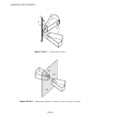
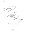
Data lines to define surfaces created with TYPE=SEGMENTS:
First line:
1. The “word” STA RT.
2. Global X-coordinate or r-coordinate of the starting point of the line segments.
18.46–5
ABAQUS Version 6.1 Module:
ID:
Printed on: