


*
REBAR
Optional parameters:
GEOMETRY
This param eter is not meaningful for rebar in beams, axisymmetric shells, or axisymmetric
membranes, or for single rebar in continuum elements.
Set GEO METRY=ISOPARAMETRIC (default) to indicate that the layer of rebar is parallel to
a direction of the element local (isoparametric) coordinate system .
Set GEOMETRY=SKEW to indicate that the rebar layer is in a skew direction with respect to
the element faces.
ISODIRECTION
Set this parameter equal to the isoparametric direction from which the rebar angle output will be
measured. The default is 1.
ORIENTATION
This parameter is meaningful only for skew rebar in shell and membrane elem ents. Set this
parameter equal to the name of an orientation definition that defines the angular orientation of
the rebar. This parameter is not permitted with axisym metric shell and axisymmetric membrane
elements.
SINGLE
This parameter is meaningful only for continuum elem ents. Include this parameter if a single rebar
is being defined by each data line. If this param eter is omitted, each line defines a layer of uniformly
spaced rebar in the element isoparametric space.
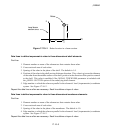
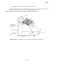
Data lines to define rebar in beam elements:
First line:
1. Element num ber or name of the element set that contains these rebar.
2. Cross-sectional area of the rebar.
3. Distance
(see Figure 17.10–1).
4. Distance
.
Repeat this data line as often as necessary. Each line defines a single rebar.
17.10–2
ABAQUS Version 6.1 Module:
ID:
Printed on: