*
IMPEDANCE
Optional parameter:
OP
Set OP=MOD (de fault) to m odify existing impedances or to define additional im pedances.
Set OP=NEW if all existing impedances applied to the model should be rem oved. To remove
only selected impedances, use OP=NEW and respecify all impedances that are to be retained.
Data line to define an impedance for PROPERTY, N ONR EFLECTING=PLANAR, or
NONREFLECTING=IMPROVED:
First (and only) line:
1. Element number or element set label.
2. Surface impedance type label, In, for impedance on face n.
Data line to define an absorbing boundary impedance for NONR EFLECTING=CIRCULAR or
NONREFLECTING=SPHERICAL:
First (and only) line:
1. Element number or element set label.
2. Surface impedance type label, In, for impedance on face n.
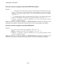
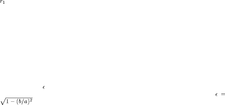
3.
, the radius of the circle or sphere defining the absorbing boundary surface.
Data line to define an absorbing boundary impedance for NONREFLECTING=ELLIPTICAL or
NONREFLECTING=PROLATE SPHEROIDAL:
First (and only) line:
1. Element number or element set label.
2. Surface impedance type label, In, for impedance on face n.
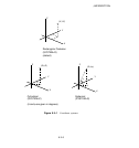
3. The semimajor axis, a, of the ellipse or prolate spheroid defining the surface. a is 1/2 of the
maximum distance between two points on the ellipse or spheroid, analogous to the radius of a
circle or sphere.
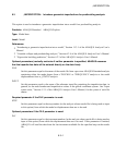
4. The eccentricity,
, of the ellipse or prolate spheroid. The eccentricity is the square root of
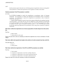
one minus the square of the ra tio of the semiminor axis, b, to the semimajor axis, a:
.
5. Global X-coordinate of the center of the ellipse or prolate spheroid defining the radiating
surface.
6. Global Y-coordinate of the center of the ellipse or prolate spheroid defining the radiating
surface.
7. Global Z-coordinate of the center of the e llipse or prolate spheroid defining the radiating
surface.
9.1–2
ABAQUS Version 6.1 Module:
ID:
Printed on:


