


*
SECTION FILE
average rigid body m otion of the surface section. This parameter is relevant only if AXES=LOCAL
and the NLGEOM param eter is active in the step.
Optional data lines:
First line:
1. Node number of the anchor point (blank if coordinates given).
2. First coordinate of the anchor point (ignored if node number given).
3. Second coordinate of the anchor point (ignored if node number given).
4. Third coordinate of the anchor point (for three-dimensional cases only; ignored if node number
given).
Leave this line blank to allow ABAQUS to define the anchor point.
Second line:
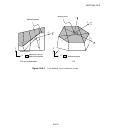
1. Node number used to specify point a in Figure 18.2–1 (blank if coordinates given).
2. First coordinate of point a (ignored if node number given).
3. Second coordinate of point a (ignored if node number given).
The remaining data items are relevant only for three-dimensional cases.
4. Third coordinate of point a (ignored i f node number given).
5. Node number used to specify point b (blank if coordina tes given).
6. First coordinate of point b (ignored if node number given).
7. Second coordinate of point b (ignored if node number given).
8. Third coordinate of point b (ignored if node number given).
Leave this line blank to allow ABAQUS to define the axes.
Third line:
1. Give the identifying keys for the variables to be output. The keys are defined in the “Section
variables” section of “ABAQUS/Standard output variable identifiers,” Section 4.2.1 of the
ABAQUS Analysis User’s Manual.
Omit both the first and second data lines for AXES=GLOBAL or to allow ABAQUS to define the anchor
point and the axes for AXES=LOCAL. Repeat the third data line as often as necessary to define the
variables to be written to the results file. If this line is omitted, all appropriate var iables (“Output to the
data and results files,” Section 4.1.2 of the ABAQUS Analysis User’s Manual) will be output.
18.2–2
ABAQUS Version 6.1 Module:
ID:
Printed on: