


5-29
INSTALLATION-DK 16 KSU & PCB
SECTION 100-816-205
MARCH 1993
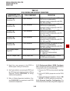
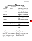
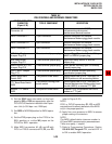
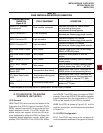
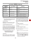
TABLE 5-F
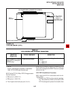
PIOU CONTROLS AND INTERFACE CONNECTORS
CONTROL/INDICATOR/
CONNECTOR
(Figure 5-18)
TYPE OF COMPONENT DESCRIPTION
SMDR/TTY Interface
Connector J3
Dual modular connector Interface connector for SMDR printer/
call accounting device and
maintenance terminal/modem.
10-pin connector
Three-terminal jumper plug
Interface connector for Remote
Maintenance Modem piggy-back module.
External Page/Door Lock Control Relay
MAKE or BREAK jumper plug.
IMDU Connector P1
M/B Make/Break
Jumper Plug P10
TTY Baud Rate Switch
SW2
Two-position locking push-
button switch
Selects baud rate (300 or 1200 bps) for
Remote Maintenance Modem piggy-back
module (IMDU) or external TTY jack.
Modem/TTY Switch
SW3
Enables PIOU for operation with IMDU
modem or TTY jack.
9-pin connector Interface connector for Remote
Maintenance Modem piggy-back module.
IMDU Connector P2
3-pin connector Interface connector for Remote
Maintenance Modem piggy-back module.
IMDU Connector P3
Three-terminal jumper plug Night/Hold Relay MAKE or BREAK
jumper plug.
M/B Make/Break
Jumper Plug P11
Three-terminal jumper plug Alarm sensor normally open or normally
closed jumper plug.
Alarm Sensor N.O./N.C.
Jumper Plug P12
Three-terminal jumper plug IMDU or external modem operating
specification jumper plug.
CCITT/BELL Jumper
Plug P13
Two-position slide switch
Selects baud rate (300 or 1200 bps) for
SMDR printer or call accounting device.
SMDR Baud Rate
Switch SW1
Two-position slide switch
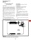
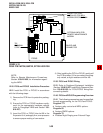
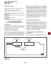
2) Set the SW2 baud rate switch on the front
panel to 300 or 1200, as appropriate, after the
PIOU/PIOUS has been installed in the Expan-
sion Unit (in-300 bps—out-1200 bps).
3) Set SW3 to MODEM position for IMDU opera-
tion.
4) Set the P13 jumper plug on the PIOU to the
BELL position; or, cut the W4 jumper on the
PIOUS for BELL operation.
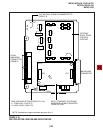
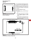
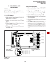
5) Mate IMDU connectors J1, J2, and J3 with
PIOU or PIOUS connectors P1, P2, and P3
(refer to Figure 5-20).
NOTE:
PIOU or PIOUS connectors P1, P2, and P3
are positioned to allow installation of the IMDU
only in the proper position.
6) Apply firm, even pressure to IMDU to ensure
proper mating of connectors.
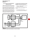
NOTE:
The IMDU default station intercom number is
619; and IMDU communication parameters are
7-bits, even parity, 1-stop bit.
7) Refer to Programming Procedures, Section
100-816-300, Program 77-1, and set LED 14
to ON to enable IMDU operation.