


8-16
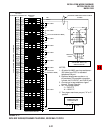
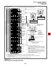
INSTALLATION-WIRING DIAGRAMS
SECTION 100-816-208
MARCH 1993
W-Bl
Bl-W
W-O
O-W
W-G
G-W
W-Br
Br-W
W-S
S-W
R- Bl
Bl-R
R-O
O-R
R-G
G-R
R-Br
Br-R
R-S
S-R
Bk-Bl
Bl-Bk
Bk-O
O-Bk
Bk-G
G-Bk
Bk-Br
Br-Bk
Bk-S
S-Bk
Y-Bl
Bl-Y
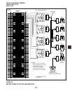
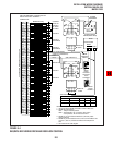
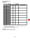
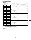
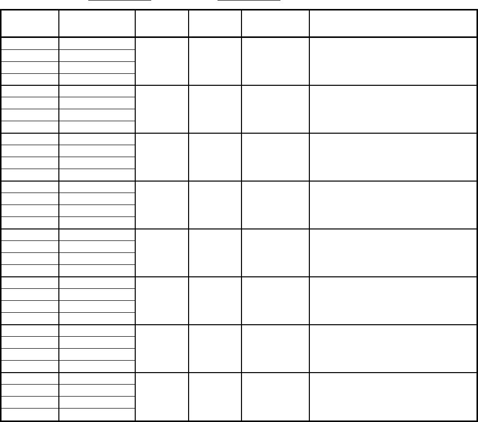
COLOR
CODE
DIGITAL TELEPHONE/
DEVICE LOCATION
T
R
PWR T
PWR R
T
R
PWR T
PWR R
T
R
PWR T
PWR R
T
R
PWR T
PWR R
T
R
PWR T
PWR R
T
R
PWR T
PWR R
T
R
PWR T
PWR R
T
R
PWR T
PWR R
DESIGNATION
CKT
NUMBER
PORT
NUMBER
INTERCOM
NUMBER
1
2
3
4
5
6
7
8
MDF BLOCK NO. SLOT NO.
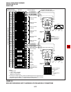
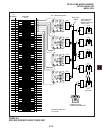
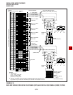
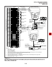
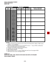
NOTES:
1. Indicate if PDIU-DS, digital telephone (with or without PDIU-DI/PDIU-DI2 or ADM) or DDSS console
(number 1 or 2) is connected.
2. PDIU-DS and PDIU-DI/PDIU-DI2 can be connected to circuits 1 ~ 7 only on PDKU1; all Base Unit,
KCDU, and PDKU2 digital circuits support DIUs.
3. Expansion Unit slots 04 and 05 only can support DIUs.
4. For KCDU, only ckt number 1 thru 4 apply.
5. Make copies as necessary.
6. PDKU and KCDU Circuit 1 can support DDCB. Base Unit Circuit 5 can support DDCB.
7. DK8 circuit 3 and or circuit 4 can support DDCB.
6
6
7
7
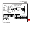
FIGURE 8-12
DK8 OR DK16 PDKU, KCDU, DK8 KSU OR DK16 BASE KSU DIGITAL STATION/MDF
CROSS CONNECT RECORD