


REMOTE ADMINISTRATION AND MAINTENANCE PROCEDURES
SECTION 100-816-600
MARCH 1993
-6-
6) For DK8 and DK16, set terminal communica-
tion parameters to seven bits, even parity,
one-stop bit (300, or 1200 bps. See step 3
above).
NOTE:
If a digital or electronic telephone is in the
program mode, programming from the main-
tenance terminal is not allowed.
4.30 Remote Maintenance Option Installation
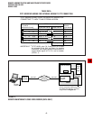
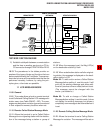
4.31 DK16 IMDU Maintenance Modem (Figure
4). The IMDU mounts on the PIOU or PIOUS PCB
and provides 300 or 1200 bps, full-duplex commu-
nication for remote maintenance (seven bits, even
parity, one-stop bit). If the IMDU is employed, a
dedicated CO line or standard telephone port is not
required. Connection of the remote maintenance
terminal is through existing system CO lines via
intercom number 619. Refer to the PIOU or PIOUS
portion of Section 200-816-205 for hardware instal-
lation and programming requirements.
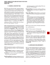
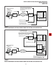
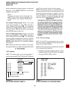
4.32 DK8 and DK16 External Maintenance Mo-
dem Installation. Refer to Figure 2 or 3, as appli-
cable, and install the external modem in accor-
dance with the following steps:
NOTE:
The Toshiba PPTC RS-232 modular-to-DB25
adaptor is factory configured for ASCII termi-
nal connection. Pins 2 and 3 and Pins 8 and 20
of the adaptor must be reversed for external
modem connection (see Table RM-A).
1) Connect the modular cord from the DK8 QSMU
or DK16 PIOU or PIOUS TTY port to the PPTC
adaptor and then to the external maintenance
modem RS-232 25-pin connector.
2) Connect the external maintenance modem
line-side to a dedicated CO line (tip and ring)
or to a dedicated standard telephone port, tip
and ring (QSTU with DK8; KSTU, PSTU, or
PESU with DK16). Refer to Wiring Diagrams,
Section 200-816-208, for wiring/interconnect-
ing details.
3) For DK16, set the PIOU or PIOUS SW2 switch
to match the modem or terminal baud rate:
Push in for 300 bps (baud rate indicator
4.10 Maintenance Terminal/External Modem
Option System Hardware Requirements
4.11 The STRATA DK8 must be equipped with a
QSMU PCB and the DK16 with a PIOU or PIOUS
PCB to support the maintenance terminal/external
modem options. Connecting the maintenance ter-
minal or external maintenance modem to the QSMU,
PIOU, or PIOUS PCB is accomplished with a
standard three-pair modular cord and a PPTC
adaptor connected to the PCB TTY jack.
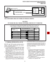
4.20 DK8 and DK16 Local Maintenance
Terminal Installation
4.21 Install the ASCII terminal in accordance with
the following steps (Figure 5):
1) Connect the three-pair modular cable (24 AWG
twisted pairs) and the PPTC adaptor from the
DK8 QSMU or DK16 PIOU or PIOUS TTY port
to the remote maintenance terminal DB25
connector.
2) For the DK8 QSMU, set Program 10-3, LED
04 ON for TTY operation.
3) For the DK16, set the PIOU or PIOUS SW2
switch to match the modem or terminal baud
rate as follows:
Push in for 300 bps (baud rate indicator
CD4 is lit); let out (by pushing again) for
1200 bps (CD4 is not lit).
NOTE:
The DK8 QSMU baud rate is always 1200 bps.
4) For DK16, set the PIOU or PIOUS SW3 switch
to the TTY position.
NOTE:
The PIOU or PIOUS SW3 switch is set to
MODEM position for IMDU operation only.
5) For DK16, set the P13 jumper plug on the
PIOU to the BELL configuration, or cut the W4
jumper on the PIOUS (also for BELL configu-
ration).
NOTE:
The P13 (PIOU) and W4 (PIOUS) CCITT
configurations are not normally used in the
USA.