


INSTALLATION-PERIPHERALS
SECTION 100-816-207
MARCH 1993
7-53
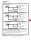
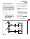
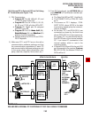
3) From PC 1’s keyboard, type A T D D 1 4 and
press ENTER (AT commands must be capi-
tal letters).
The Data Call LED on DKT 14 will be lit.
The CONNECT LED on PDIU-DS 14 will
be lit.
The screen on PC 1 displays, CON-
NECT XXXX, where XXXX is the data
transmission speed set by the communi-
cations software.
At this time, PC 1 and PDIU-DS 14 are
connected as shown by the thick lines
above (PDIU-DS 14 is in the communica-
tion mode); PC 1 is now linked directly to
the RS-232 side of the internal modem;
PC 1 can issue AT commands to the
internal modem, which is now in the
command mode.
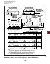
If Digital/PDIU-DS port 04 is the only DIU
port connected to the modem (Program
20, LED 03 ON), the Modem LEDs on all
DKTs will be lit.
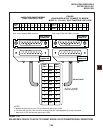
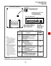
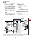
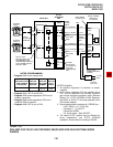
10.84 Internal PC to External PC Test Call Using
AT Commands (see Figure 7-36)
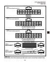
1) DIU Programming:
Program 20: Port 00. LEDs 01, 02, and
17 ON; all other LEDs OFF.
Program 20: Port 04. LEDs 01, 02, 03,
04, 06, and 17 ON; all other LEDs OFF.
Program 21: Digital port 04 assigned
with KSTU port 08.
Program 39: Port 00. Data Call (56),
Data Release (54), and Modem (55)
buttons should be provided.
Default settings for PDIU-DI and PDIU-
DS S-Registers.
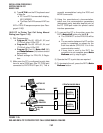
2) Make sure PC 1 and PC 2 are on-line with a
communications software package and that
the communication parameters of each PC
and communication software package are set
to the same values (data transmission rate,
parity, data bits, stop bits, flow control, etc.).
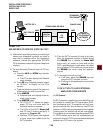
FIGURE 7-36
DK8 AND DK16 INTERNAL PC TO EXTERNAL PC TEST CALL USING AT COMMANDS
QSTU OR
KSTU
(PORT 08)
DIGITAL
(PORT 04)
DIU
POWER READYCONNECT
TOSHIBA
MDF
RS-232
INTERNAL
MODEM
(18)
PDIU-DS
(14)
EXTERNAL
MODEM
(AUTO
ANSWER)
MDF
CO
LINE 1
PUBLIC
TELEPHONE
NETWORK
583-3700
TELEPHONE
LINE
674-4700
RS-232
LAPTOP
PC 2
STRATA DK8 OR DK16
DIGITAL
(PORT 00)
LAPTOP PC 1
RS-232
DKT/PDIU-DI
(10)
MDF