


INSTALLATION-PERIPHERALS
SECTION 100-816-207
MARCH 1993
7-11
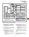
5) Access Programs 29-1 ~ 29-2 to program a
Night Transfer button (NT1 or NT2) on all
DSS consoles that are to transfer the system
into the NIGHT mode.
6) If tenant operation is required, access Pro-
gram 15 to set the CO lines for tenant 1 (NT1)
or tenant 2 (NT2) operation.
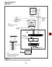
7A) Set the P11 jumper plug on the PIOU to the
MAKE or BREAK position, as required:
MAKE—Shorts the normally open con-
tacts (pins 9 and 34) when the night relay
is activated.
BREAK—Opens the normally closed
contacts (pins 9 and 34) when the night
relay is activated.
7B) Solder the jumper W2 on the PIOUS to the
MAKE or BREAK position, as required:
MAKE—Shorts the normally open con-
tacts (NHT and NHR) when the night
relay is activated.
BREAK—Opens the normally closed
contacts (NHT and NHR) when night
relay is activated.
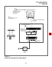
8) Refer to Figures 7-6 and 7-7 for wiring/inter-
connecting details. Connect the PIOU or PI-
OUS to the MDF as required for the night relay
function.
NOTE:
Door phones programmed to ring over exter-
nal page in night mode (Program 77-1) do not
activate the NT relay.
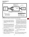
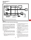
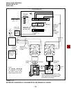
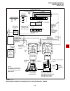
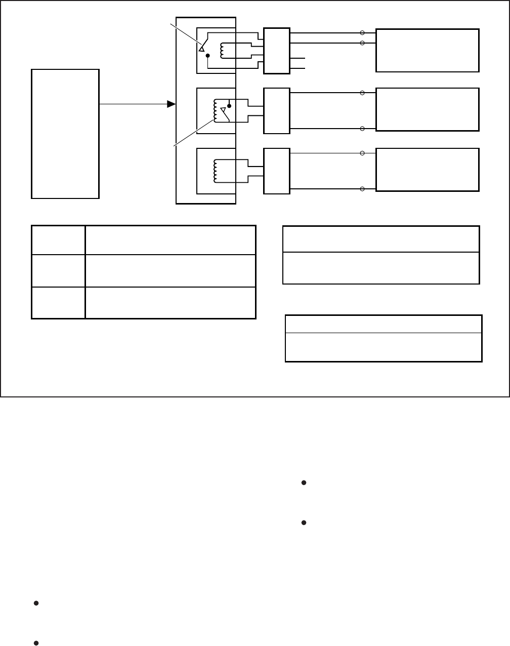
FIGURE 7-9
DK8 AND DK16 DOOR LOCK CONTROL OPTION (DDCB)
DK16 KDCU,
CKT1
- OR-
DK16 PDKU,
CKT1
- OR -
DK16 DIGITAL
CKT5 OF
BASE UNIT
- OR -
DK8 KSU,
CKT 3 AND 4
(See Fig. 8-4
wiring diagrams)
(DK16 Port 04, 12)
(DK8 Port 02, 03)
DDCB
A
C
2
B
3
4
5
RJ11
3
4
2
5
TO CUSTOMER
SUPPLIED
DEVICE
MDFB
1
2
RJ11
3
4
MDFB
1
RJ11
3
4
MDFB
1
3
4
DOOR PHONE
A
DOOR PHONE
B
- or -
DOOR LOCK CONTROL
2
2
DOOR PHONE
C
3
4
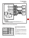
DDCB TO DK16 BASE UNIT WIRING CHART
BASE UNIT
AMPHENOL
TO DDCB KSU JACK
DT (34) / DR (9)
PT (35) / PR (10)
TO
TO
PIN 3 / 4
PIN 5 / 6
DDCB TO DK16 EXPANSION UNIT
WIRING CHART
KCDU OR PDKU
TO DDCB KSU JACK
DT (26) / DR (1) TO PIN 3 / 4
See Figure 8-4 for DK16 Base Unit, PDKU, and
KCDU pin-out information
NOTES
1.
2.
3.
Relay control contact will close when the door phone is in the
ringing, talk, or monitor state.
See Paragraph 4.25 for Door Lock assignments.
Relay contact specifications are -24VDC at 1.0 amp. max. Do
not connect relay contacts to 120 AC commercial power.
NOTE 1
RELAY
CONTROL
CONTACT
DOOR LOCK
CONTROL
CONTACT
NOTE 2
PT (27) / PR (2) TO PIN 5 / 6
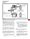
DDCB TO DK8 KSU WIRING CHART
PORT NO.
TO
DDCB
KSU JACK
DT (30) / DR (5)
PT (31) / PR (6)
DT (32) / DR (7)
PT (33) / PR (8)
TO
TO
TO
TO
PIN 3 / 4
PIN 5 / 6
PIN 3 / 4
PIN 5 / 6
DK8 AMPHENOL
02
03