


INSTALLATION-STATION APPARATUS
SECTION 100-816-206
MARCH 1993
6-8
version) and the integrated data interface
unit (PDIU-DI) at the same time, but 2000-
series digital telephones can support an
HHEU and a PDIU-DI2 at the same time.
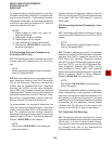
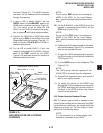
3.32 HHEU Upgrade Installation (HHEU) Install
the Loud Ringing Bell/headset upgrade (HHEU) in
accordance with the following steps.
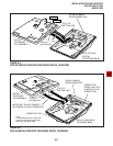
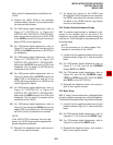
1) Loosen the four captive screws securing the
telephone base (Figure 6-1), and remove the
base.
2) Using a screwdriver or other suitable tool,
remove the plastic tab located on the back of
the base (Figure 6-1); the HHEU modular
connector for the headset will be accessed
through this opening.
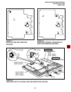
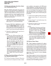
3) If installing a V.3 HHEU1, set the SW601
switch on the HHEU to HEADSET for the
headset or loud bell application (Figure 6-10).
V.4 HHEU1 and HHEU2 do not have this
switch, because both of these upgrades are
automatically set for the headset/loud bell
application.
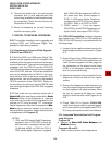
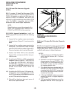
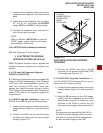
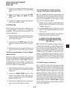
4) Connect the HESC-65A cable to P601 of the
HHEU (both HHEU1A versions and the
HHEU2 have P601) if the Loud Ringing Bell
option is required (Figure 6-11). Refer to
Section 100-816-207 for HESB installation
procedures.
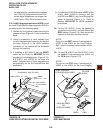
5A) For the V.3 HHEU1: If only the headset is
connected to the HHEU, cut both sides of the
R607 resistor (Figure 6-10), then remove the
resistor to eliminate electrical contact.
NOTE:
Do not cut the R607 resistor if connecting an
HESB to the HHEU for the Loud Ringing
Bell—even if a headset is also installed on the
HHEU.
5B) For the V.4 HHEU1 and the HHEU2: If only
the headset is connected to the HHEU, cut
the OCA strap (Figure 6-10).
NOTE:
Do not cut the OCA strap if connecting an
HESB to the HHEU for the Loud Ringing
FIGURE 6-10
HHEU INSTALLATION FOR DIGITAL TELEPHONE
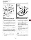
FEED THROUGH
FOR HESC-65(A) CABLE
TO HESB
BLOCK
SW601
HHEU
P601
HESC-65 CABLE
OR
HESC-65A CABLE
HHEU
COMPONENT SIDE OF HHEU
SW601
P601
R607 (HHEU1 V.1 ~ V.3)
OCA (HHEU1
(HHEU1 V.1 ~ V.3)
V.4 or HHEU2)
FIGURE 6-11
HESC-65A CABLING