


INSTALLATION-CONFIGURATION
SECTION 100-816-203
MARCH 1993
3-6
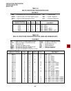
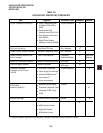
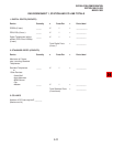
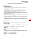
TABLE 3-F
PIOU/PIOUS INTERFACE OPTION (DK16 ONLY)
NOTE: X = the option is provided
Expansion Unit Interface Options PIOU PIOUS
Zone Page Interface (unamplified, 4 zones)
Night Transfer or Music-on-Hold Control Relay
Door Lock or External Amplifier Control Relay
Alarm Sensor
SMDR output (RS-232/6-wire modular connector)
Maintenance Port for a Local ASCII Terminal or
External Modem (RS-232/6-wire modular connector)
Remote Maintenance Modem (IMDU subassembly, no
external connector)
X
X
X
X
X
X
X
X
X
X
X
X
X
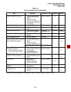
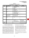
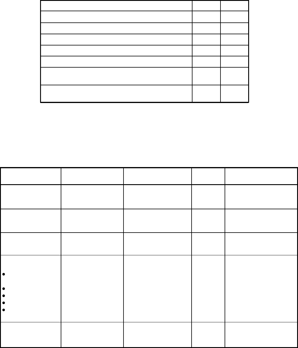
TABLE 3-G
STRATA DK8 STATION APPARATUS OVERVIEW
Type and Number of
Circuits Required
Digital, one for each
DKT
Digital, one for each
PDIU-DS
Digital, one for each
DDCB
Standard, one for
each device (voice
mail devices may
require more than one
circuit)
Standard port for the
source
KSU
Capacity
4
4
2
—
1
KSU and Optional PCB
Combined Capacity
8
8
2
2
1
Station
Digital Telephone
DKT with or without
ADM or PDIUDI
Stand-alone Data
Interface Unit (PDIU-
DS)
Digital Door
Phone/Lock Control
Unit (DDCB)
Single-wire pair
devices:
Standard
Telephone
Voice Mail Device
Facsimile Machine
Modem
Dictation
Equipment
Alternate
Background Music
Source
*
PCB or Interface
KSU (Circuits 1 ~ 4)
QCDU (Circuits 1 ~ 2)
KSU (Circiuts 1 ~ 4)
QCDU (Circuits 1 ~ 2)
KSU Port 02
Port 03
QSTU (Circuits 1 ~ 2)
QSTU (Circuit 2)
Port 19
*
May require interface transformer, see Section 100-816-207.