


FAULT FINDING
SECTION 100-816-500
MARCH 1993
-1-
as described in
Programming Procedures.
It is very important to verify that the sys-
tem programming is correct and func-
tional before troubleshooting the hard-
ware.
3.02 Initialize the system (Program 90, 92, and
03) before testing new systems or when in DK16
cases,, changing the KFCU, Feature cartridge (if
instructions specify).
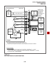
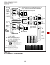
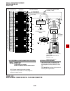
3.03 Faults in the DK8 and DK16 are cleared by
replacing PCBs, telephones (digital or electronic)
or the power supply, as instructed in the flow-
charts.
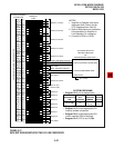
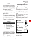
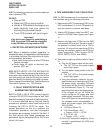
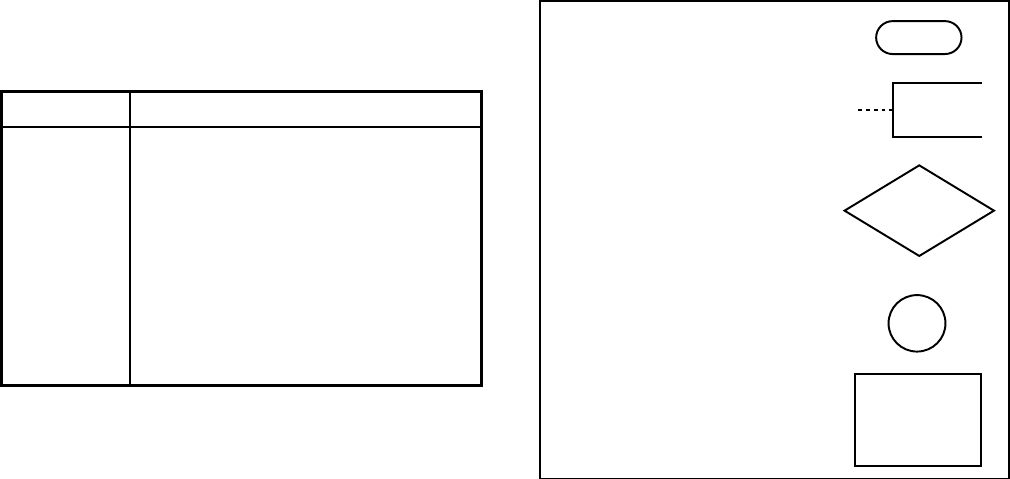
3.04 Five symbols are used in the flowcharts,
which are identified in Figure 1.
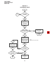
3.05 The flowcharts are sequentially arranged to
permit rapid fault localization within the system.
All
fault clearing must begin with the Fault Classifica-
tion Flowchart
, which is arranged in the correct
1 GENERAL
1.01 This section describes the maintenance pro-
cedures used to diagnose faults in the STRATA
DK8 and DK16 digital key telephone system. Faults
are classified and then cleared by replacing the
malfunctioning unit and performing operational
tests in the sequences prescribed by the fault
clearing flowcharts in Paragraph 9.
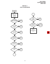
2 FAULT CLASSIFICATION
2.01 A Fault Classification Flowchart is provided to
ensure that fault clearing is pursued in a logical
sequence (Chart No. 1).
2.02 An assumption is made in the flowcharts that
the fault was discovered and reported by a digital
or electronic telephone user. All faults, therefore,
are classified according to the way they would
appear at the digital or electronic telephone.
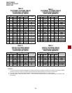
2.03 Faults and associated flowcharts in Table A
are organized into the following categories:
Flowchart
TABLE A
FLOWCHARTS
Title
Fault Classification
Catastrophic Faults
Station Dial Tone Faults
CO Line Dial Tone Faults
DSS Console Faults
Voice Mail/(External) Auto Attendant
(VM/AA) Faults
Station Message Detail Recording
(SMDR) Faults
Remote Maintenance Faults
1
2
3
4
5
6
7
8
3 FAULT CLEARING PROCEDURES
3.01 Before attempting to clear any fault, ensure
that it is in the system and not caused by associ-
ated external equipment, such as wiring, MOH
source, etc.
IMPORTANT!
Many system features are assigned, en-
abled or disabled using software entries
Progression TO or FROM
another flowchart location.
Letters and numbers denote
the exact entrance or exit
points.
Important notes affecting the
fault clearing procedure.
Marking points of a
flowchart sequence.
Question to be answered
YES or NO.
Statement of a required
action.
FIGURE 1
FLOWCHART SYMBOLS
fault locating sequence.