


INSTALLATION-DK8 KSU & PCB
SECTION 100-816-204
MARCH 1993
4-9
PART II. PRINTED CIRCUIT BOARD
INSTALLATION
5 GENERAL
5.01 This chapter provides procedures for installa-
tion of STRATA DK8 system optional printed circuit
boards (PCBs) into the Key Service Unit. This
includes installation instructions, optional configu-
ration information, and wiring and programming
considerations for each PCB.
5.02 Be sure the ground has been checked. (See
Chapter 2 for grounding.)
6 PCB INSTALLATION
CONSIDERATIONS
6.01 The STRATA DK8 KSU comes standard with
four digital telephone circuits (ports) and two CO
line circuits. These circuits, along with the common
control unit, are built into the motherboard.
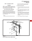
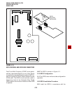
6.10 KSU Option PCBs
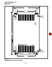
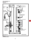
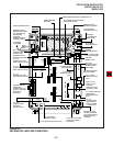
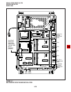
6.11 The KSU can support up to five optional
printed circuit boards (PCBs) (Figure 4-7): it can
support a maximum of two QCDUs, each of which
provides one CO line circuit and two digital tele-
phone circuits; a QSTU which provides two stan-
dard telephone circuits (ports); a QRCU which
provides three circuits to receive DTMF tones
(required for DISA and devices connected to
QSTUs), and three circuits to detect busy tone
(required for the ABR feature); and a QSMU which
provides a port for either a Station Message Detail
Recording (SMDR) device or a maintenance termi-
nal or modem (System Program 10-3, LED 04)
selects the function of the port — SMDR or TTY).
6.12 The KSU does not come from the factory with
any option PCBs installed. Each of the option
PCBs listed above must be installed in specific
locations as described later in this chapter.
NOTE:
QCNU is a standard factory installed piggy-
back PCB which provides conference circuits
allowing two simultaneous conferences with
four of these parties on the first conference
call and three parties on the second simulta-
neous conference.
6.20 PCB Option Considerations
6.21 PCBs may be configured for a variety of
hardware and software options. Hardware options
are defined as either internal (generally related to
optional PCB subassemblies) or external (related
to connection of peripheral equipment such as
background music, voice mail, etc). Hardware and
software options for each PCB are identified in the
individual PCB installation procedures in this chap-
ter.
6.22 PCB Hardware Options. Each PCB must be
configured for the applicable hardware options
prior to installation of the PCB. Configuration in-
structions for internal hardware options are pro-
vided in the individual PCB installation procedures
in this chapter. Configuration instructions for exter-
nal hardware options are provided in Peripheral
Installation, Section 100-816-207.
6.23 PCB Software Options. PCBs are config-
ured for software options through programming,
after installation of the PCBs in the KSU. A pro-
gramming overview for each PCB is provided in the
individual PCB installation procedures in this chap-
ter. Refer to the Programming Procedures, Section
100-816-300, for detailed programming instruc-
tions.
6.30 PCB Installation/Power Supply Consid-
erations
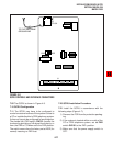
6.31 Whenever removing or installing PCBs it is
recommended that the power supply be OFF.
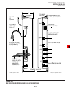
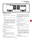
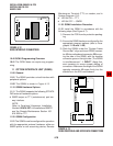
7 CO LINE/DIGITAL TELEPHONE
INTERFACE UNIT (QCDU)
7.00 General
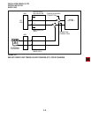
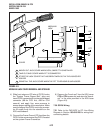
7.01 The QCDU provides one loop start CO line
circuit and two digital telephone circuits. The QCDU
digital telephone circuits can support digital tele-
phones, PDIU-DIs/PDIU-DI2s or ADMs connected
to the telephones and PDIU-DSs. The QCDU does
not support a DDSS console or DDCB. A maximum
of two QCDU PCBs may be installed in the KSU.